


BDM-610000049 Rev G Chapter 4: Using the cpuModule 65
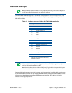
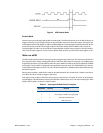
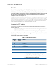
Figure 6 aDIO Match Mode
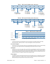
Strobe Mode
Another interrupt mode supported by aDIO is Strobe mode. This allows the strobe pin of the DIO connector to
trigger an interrupt. A low to high transition on the strobe pin will cause an interrupt request. The request will
remain high until the Clear Register is read from. Additionally, the Compare Register latched in the value at Port
0 when the Strobe pin made a low to high transition. No further strobes will be available until a read of the
Compare Register is made. You must read the Compare Register, and then clear interrupts so that the latched
value in the compare register is not lost. To enter Strobe mode, set bits [4:3] of the DIO-Control register to “01”.
Wake-on-aDIO
The aDIO Strobe, Match and Event interrupt can be used to generate a wake event. This event can wake the CPU
from any power-down mode, including Soft-Off (S5). Wake from aDIO will work as long at +5V Standby power
is applied to the board. To use the aDIO to wake the system, Wake from aDIO must first be enabled in the BIOS
setup utility. Then the aDIO is configured in the appropriate interrupt mode. The “Wake Enable” bit is then set
in the Wake Control Register at 0x454. The CPU can then be placed in a standby mode, and the aDIO interrupt
will wake the system.
During system standby, a 32kHz clock is used for the aDIO instead of an 8.33 MHz clock. Therefore, transitions
must be at least 30 us in order to trigger a wake event.
If the aDIO is to be used for a wake event only, and not an interrupt, the “Int Mask” bit can be set in the Wake
Control Register. This will block the interrupt, but still allow a wake event to occur. The various settings for “Wake
Enable” and “Int Mask” are shown in Table 51 below.
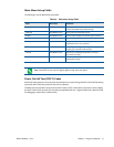
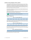
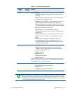
Table 51 Interrupt and Wake Event Generation
WakeEnable Int Mask Function
0 0 Interrupt Only
0 1 No Interrupt or Wake event is generated
1 0 Interrupt and Wake Event
11 Wake Event Only