


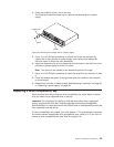


4. Close the handle to move it out of the way.
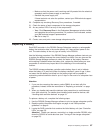
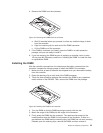
The following illustration shows how to remove the release tab on a power
supply.
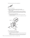
5. Use a #1 or #0 Phillips screwdriver to remove the screw that secures the
release tab to the controller or power supply; then, remove the release tab.
Save the screw to install the new release tab.
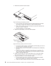
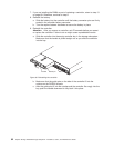
6. Insert the alignment pins on the release tab into the holes in the left front of the
controller or power supply and hold it in place.
Note: The arrow on the outside of the release tab points to the right.
7. Use a #1 or #0 Phillips screwdriver to install the screw that you removed in step
5.
8. Press the release tab gently to the right and open the handle on the controller
or power supply.
9. Reinstall the controller or power supply. See“Replacing a controller” on page 66
or “Replacing a power supply” on page 82.
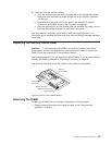
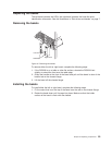
Replacing a drive compatibility key
Each hard disk drive bay contains a drive compatibility key, which helps to ensure
that you install only a supported drive in the bay.
Important: Do not attempt to install any hard disk drive other than a supported
drive in any hard disk drive bay. Seehttp://www.ibm.com/systems/storage/disk/
ds3000/ds3200/ for information about the DS3200 and an interoperability matrix that
lists supported hard disk drives.
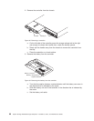
If a drive compatibility key breaks, you must replace it. The miscellaneous hardware
kit contains several replacement drive compatibility keys; obtain a kit if you have to
replace a drive compatibility key (see Table 9 on page 110).
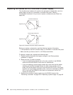
Handle
Release tab
Screw
Figure 59. Removing the release tab on a power supply
Chapter 5. Replacing components 95