


Overview of steps to connect storage expansion enclosures to a
storage subsystem
To connect storage expansion enclosures to the storage subsystem, complete the
following steps:
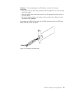
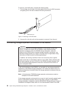
1. Follow the instructions in the Installation, User's, and Maintenance Guide for
your storage expansion enclosure and the Rack Installation Instructions to set
up and mount the storage expansion enclosures.
2. Select a cabling topology applicable to the number of ESMs in the storage
expansion enclosures that you will connect to the DS3200. If you are connecting
external storage expansion enclosures to the DS3200, make sure that each
storage expansion enclosure contains at least four drives before you power it
on. In addition, make sure that the DS3200 storage subsystem contains at least
four drives before you power it on.
“DS3200 storage subsystem drive cabling topologies” describes the
recommended schemes for cabling storage expansion enclosures with one ESM
or two ESMs to the DS3200 and to each other (if you are connecting more than
one storage expansion enclosure).
3. Follow the cabling diagram for your chosen topology.
4. If required, set unique enclosure IDs for all storage expansion enclosures that
are cabled to the DS3200. See the DS3000 Storage Manager Version 2
Installation and Support Guide for information about setting the enclosure ID.
The DS3200 storage subsystem locates the drives in the storage expansion
enclosures after you power-on the configuration. Always turn on the storage
expansion enclosures first and then turn on the DS3200. After you have
powered-on the configuration, use the DS3000 Storage Manager software to check
the status of the new drives, correct any errors, and configure the new drives.
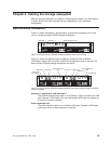
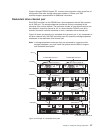
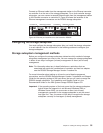
DS3200 storage subsystem drive cabling topologies
This section describes the following preferred cabling topologies for cabling storage
expansion enclosures to the DS3200 storage subsystem:
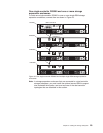
v “One single-controller DS3200 and one or more storage expansion enclosures”
on page 29
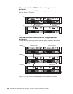
v “One dual-controller DS3200 and one storage expansion enclosure” on page 30
v “One dual-controller DS3200 and two storage expansion enclosures” on page 30
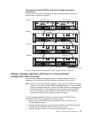
v “One dual-controller DS3200 and three storage expansion enclosures” on page
31
Each example provides redundant paths to the drives. If one of these examples is
suitable for your hardware and application, complete the cabling connections as
shown in the illustrations. If you have hardware other than what is shown in these
examples to include in your topology, use these examples as a starting point for
creating your specific topology.
Important:
1. The DS3200 supports the connection of a maximum of three storage expansion
enclosures.
2. The DS3200 supports one redundant drive-channel pair.
3. In storage expansion enclosures that are connected to a dual-controller storage
subsystem, you must install the optional second ESM to support dual redundant
drive paths.
28 System Storage DS3200 Storage Subsystem: Installation, User’s, and Maintenance Guide