


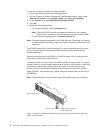
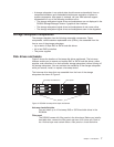
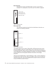
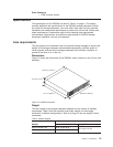
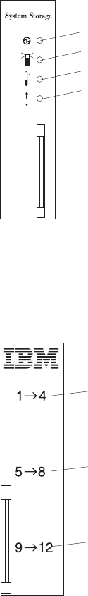
Bezel (left side)
The left bezel contains the DS3200 LEDs, as shown in the following
illustration. For a description of the LEDs, see “Front LEDs” on page 53.
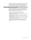
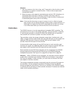
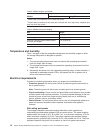
Bezel (right side)
The right bezel contains the hard disk drive identification information, as
shown in the following illustration.
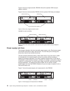
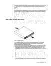
The DS3200 supports up to twelve 3 Gbps SAS or SATA hard disk drives, which
come preinstalled in drive trays. Install drives in the 12 drive bays on the front of
the storage subsystem. When a drive is installed, the drive and tray bay designation
is set automatically. The hardware addresses are based on the enclosure ID setting
on the controller and on the physical locations of the drives in the storage
subsystem.
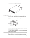
There are no serviceable parts in a drive assembly. If it fails, it must be replaced in
its entirety (drive, bezel, and tray). When you replace a drive, be sure to order and
install the correct drive. Using a nonsupported drive causes the drive to be locked
out by the DS3200 controller firmware.
Power-on LED
System locator LED
System error LED
Overtemperature LED
Figure 3. Bezel (left side)
Drives 1 - 4
Drives 5 - 8
Drives 9 - 12
Figure 4. Bezel (right side)
8 System Storage DS3200 Storage Subsystem: Installation, User’s, and Maintenance Guide