


38 Hardware Maintenance Manual: xSeries 200
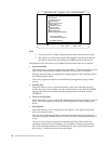
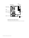
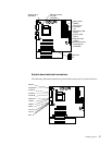
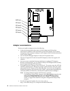
System board switches and jumpers
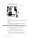
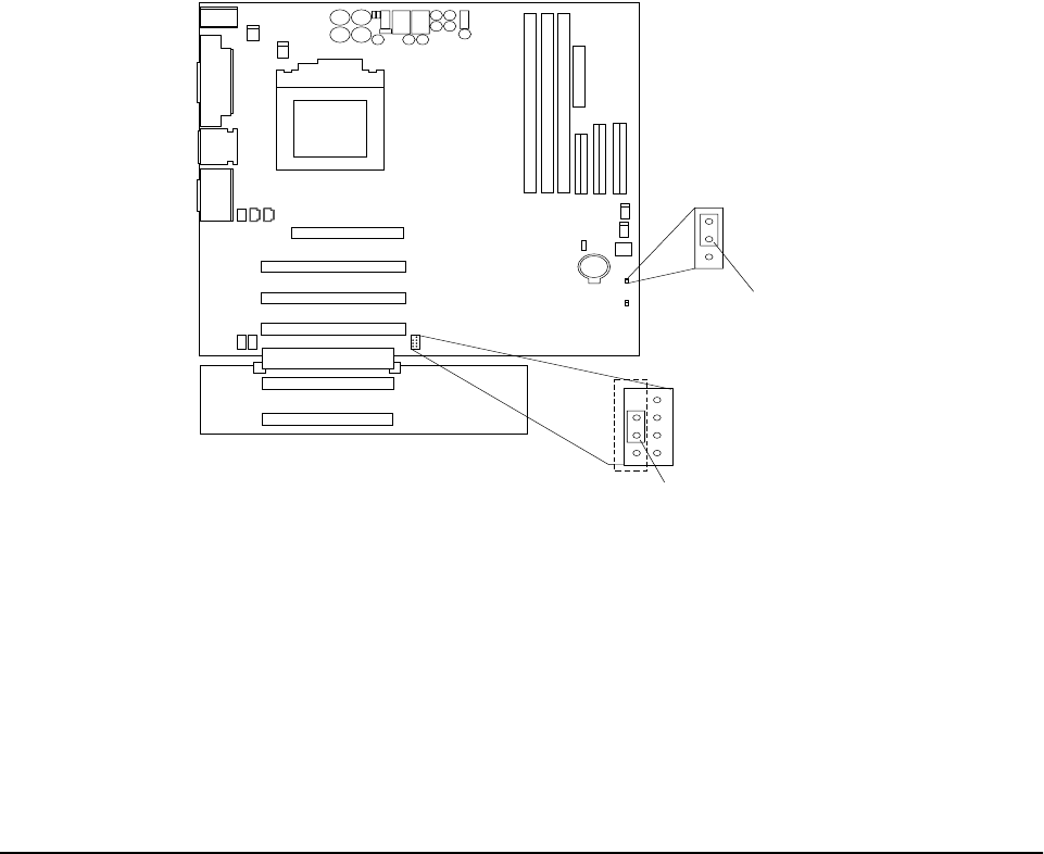
The following illustration identifies the switches and jumpers on the system board.
Boot block jumper
For normal operations of the system, a jumper is installed on pins 2 and 3 of the boot
block jumper. See “Recovering BIOS” on page 14 for information about the boot block
jumper.
CMOS jumper
For normal operation of the system, a jumper is installed on pins 1 and 2 of the
complimentary metal oxide semiconductor (CMOS) jumper. See “Clearing CMOS” on
page 15 for information about the CMOS jumper.
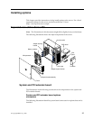
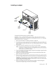
Before you begin
Before you begin to install options in the server, read the following information:
• Become familiar with the safety and handling guidelines provided in:
—“Safety information” on page 105;
—“Handling electrostatic discharge-sensitive devices” on page 108; and
—“Safety notices (multi-lingual translations)” on page 109.
These guidelines will help you work safely while working with the server or
options.
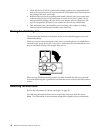
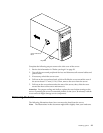
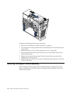
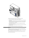
• When you need to access the inside of the server to install options, you might find
it easier to lay the server on its side. If you do so, rotate the two front feet in
towards the server, so they do not break off due to the weight of the server.
CMOS jumper
(JBAT1)
Boot block jumper
(JROM1)
1
1
2
2
3
3