


68 Hardware Maintenance Manual: xSeries 200
3. In Windows NT, VLANs cannot be implemented on controllers that have been
configured for teaming options. NetWare can support teaming options and
VLANs on the same adapters.
Complete the following steps to join a VLAN from Windows NT 4.0:
1. Create a VLAN on the switch. Use the parameters you assign there to join the
VLAN from the server. Refer to your switch documentation for more information.
2. Double-click the Network icon in the Control Panel window.
3. On the Adapters tab, select the adapter you want to be on the VLAN and select
Properties.
4. In IBMSet, select Join VLAN. Note that VLANs cannot be assigned to adapters
that are already defined to have an adapter teaming option.
5. Enter the VLAN ID and VLAN name. The VLAN ID must match the VLAN ID of
the switch. The ID range is from 1 to 1000. The VLAN name is for information
only and does not need to match the name on the switch.
6. Select Join VLAN. Repeat steps 3 through 5 for each VLAN you want the server
to join. The VLANs you add are listed on the Adapters tab.
7. Select Close and restart the computer.
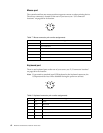
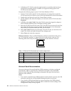
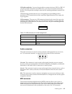
Ethernet connector: There is an RJ-45 Ethernet connector on the back of the server,
see “I/O connector locations” on page 60 for the location of this connector. The
following table shows the pin-number assignments for the Ethernet connector.
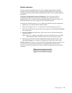
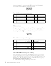
Universal Serial Bus connectors
Your server has two Universal Serial Bus (USB) connectors, which are configured
automatically. USB is a serial interface standard for telephony and multimedia
devices. It uses Plug and Play technology to determine the type of device that is
attached to the connector.
Notes:
1. If you attach a standard (non-USB) keyboard to the keyboard connector, the USB
connectors and devices will be disabled during the power-on self-test.
2. If you install a USB keyboard that has a mouse connector, the USB keyboard
emulates a mouse, and you will not be able to disable the mouse settings in the
Configuration/Setup Utility program.
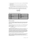
Table 11. Ethernet RJ-45 connector pin-number assignments..
Pin Signal Pin Signal
1 + Transmit data 5 Not connected
2 - Transmit data 6 - Receive data
3 + Receive data 7 Not connected
4 Not connected 8 Not connected
8
1