


Installing options 51
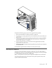
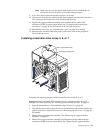
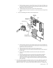
Note: Make sure to route the signal cable so that it does not block the air
flow to the rear of the drives or over the microprocessor.
9. If you have other options to install or remove, do so now.
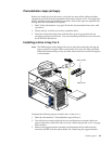
10. Connect one of the power cables from the power supply into the back of the drive.
The connectors are keyed and can be inserted only one way.
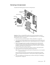
11. Replace the support bracket assembly and reconnect the fan cable to the
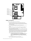
connector (SYSFA3) on the system board. See “System board internal cable
connectors” on page 36 for the location of the fan cable connector.
12. Reinstall the side cover, see “Installing the cover” on page 59 for details.
13. Reconnect the external cables and power cords; then, turn on the peripheral
devices and the server.
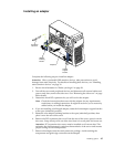
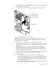
Installing a hard disk drive in bay 5, 6, or 7
Complete the following steps to install a hard disk drive in bay 5, 6, or 7.
Attention: When you handle ESD-sensitive devices, take precautions to avoid
damage from static electricity, see “Handling static-sensitive devices” on page 39.
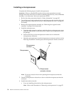
1. Read the information in “Preinstallation steps (all bays)” on page 49.
2. Turn off the server and peripheral devices and disconnect all external cables and
power cords; then, remove the cover (see “Removing the side cover” on page 40
for details).
3. Remove the support bracket assembly. See “Removing the support bracket
assembly” on page 42.
4. Remove the support bracket assembly and disconnect the fan cable from the
connector (SYSFA3) on the system board. See “Removing the support bracket
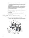
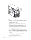
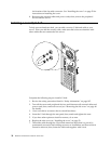
Drive cage release tab
Drive cage retention tab