


70 Hardware Maintenance Manual: xSeries 200
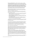
locations” on page 60 for the location of the MIDI connector. The following table
shows the pin-number assignments for the MIDI connector.
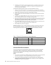
Video connector
Your server uses an AGP adapter located in the AGP slot on the system board. There
is a 15-pin analog video connector located on the rear of the server. See “I/O
connector locations” on page 60 for the location of this connector. The table below
shows the pin-number assignments for the video connector.
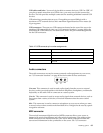
Ultra 3/160 SCSI connector (some models)
Some xSeries 200 server models come with a SCSI adapter, which supports a single
Ultra 3/160/MB SCSI channel in a full-featured PCI 2.1-/2.2-compliant bus master
package. This configuration supports a zero wait state, 32-bit memory transfers at 160
Mbytes/second, when LVD SCSI peripherals are attached. This channel supports up
to 15 SCSI devices. In addition, this adapter uses:
• Double-transition clocking to achieve high transfer rates
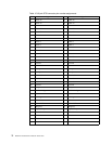
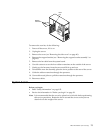
Table 13. MIDI connector pin-number assignments.
Pin Signal Pin Signal Pin Signal
1 +5 V 6 Joystick 1 -- Y 11 Joystick 2 -- X
2 Joystick 1 Switch A 7 Joystick 1 Switch B 12 MIDI - OUT
3 Joystick 1 -- X 8 +5 V 13 Joystick 2 -- Y
4 Switch Common 9 +5 V 14 Joystick 2 Switch D
5 Switches Common 10 Joystick 2 Switch C 15 MIDI - IN
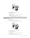
Table 14. Video connector pin-number assignments.
Pin Signal Pin Signal Pin Signal
1Red 6Ground11Not connected
2 Green or monochrome 7 Ground 12 DDC SDA
3 Blue 8 Ground 13 Horizontal synchronization
(Hsync)
4Not connected 9+5 V dc
DDC
14 Vertical synchronization (Vsync)
5 Ground 10 Ground 15 DDC SCL
8
1
15 9
1
5
1115