


Installing options 65
3. When the Configuration/Setup Utility menu appears, select Devices & I/O Ports;
then, press Enter.
4. Select the serial connector; then, use the arrow keys to advance through the
available settings.
5. Press Esc twice to return to the Configuration/Setup Utility main menu; then,
select Save & Exit Setup to exit from the Configuration/Setup Utility main menu.
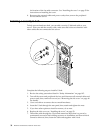
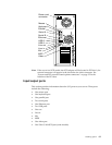
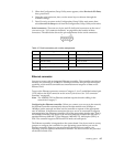
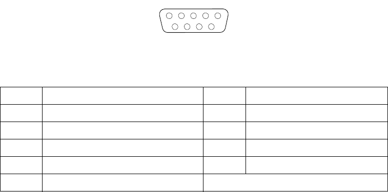
Serial connectors: There are two 9-pin, male D-shell serial connectors on the rear of
your server, see “I/O connector locations” on page 60 for the location of these
connectors. The table below shows the pin-assignments for the serial connectors.
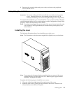
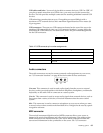
Ethernet connector
Your server comes with an integrated Ethernet controller. This controller provides an
interface for connecting to 10-Mbps or 100-Mbps networks and provides full-duplex
capability, which enables simultaneous transmission and reception of data on the
Ethernet LAN.
To access the Ethernet connector, connect a Category 3, 4, or 5 unshielded twisted-pair
(UTP) cable to the RJ-45 connector on the rear of your server. See “I/O connector
locations” on page 60.
Note: The 100BASE-TX Fast Ethernet standard requires that the cabling in the
network be Category 5.
Configuring the Ethernet controller: When you connect your server to the network,
the Ethernet controller automatically detects the data-transfer rate (10Mbps or
100Mbps) on the network and then sets the controller to operate at the appropriate
rate. In addition, if the Ethernet connector that your server is connected to supports
auto-negotiation, the Ethernet controller will set the appropriate duplex state. That is,
the Ethernet controller will adjust to the network data rate, whether the data rate is
standard Ethernet (10BASE-T), Fast Ethernet (100BASE-TX), half duplex (HDX), or
FDX. The controller supports HDX and FDX modes at both speeds.
The Ethernet controller is integrated on the system board. You do not need to set any
jumpers or configure the controller for your operating system before you use the
Ethernet controller. However, you must install a device driver to enable your
operating system to address the Ethernet controller. The device drivers are provided
on the ServerGuide CDs.
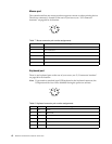
Table 10. Serial connectors pin-number assignments.
Pin Signal Pin Signal
1 Data carrier detect 6 Data set ready
2 Receive data 7 Request to send
3 Transmit data 8 Clear to send
4 Data terminal ready 9 Ring indicator
5 Signal ground
1
5
69