


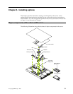
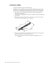
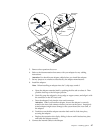
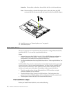
Chapter 5. Installing options 41
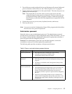
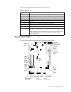
The following table describes the function for each switch.
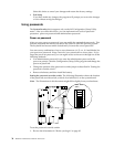
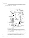
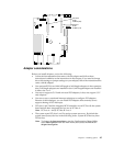
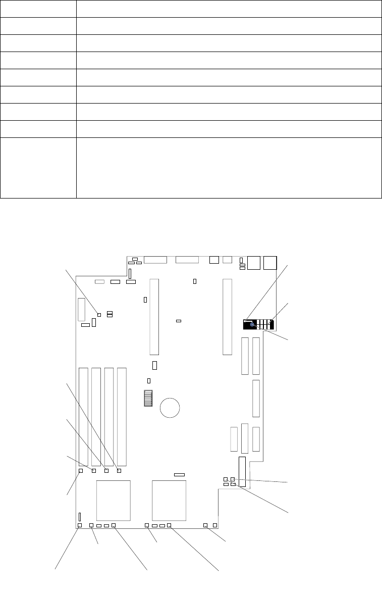
System board LEDs
The following illustration identifies the LEDs on the system board.
Table 9. Switches 1-8.
Switch number Switch description
1 Reserved.
2 Reserved.
3 Reserved.
4 Reserved.
5 Force power-on. The default setting is Off (disabled).
6 Reserved. The default setting is Off.
7 Reserved. The default setting is Off.
8 Bypass power-on password.
When toggled to the opposite position, bypasses the power-on password,
if one is set, for one boot cycle. See “Setting the password override
switch” on page 34.
Light path
diagnostic circuit
verification LED
Light path
diagnostics
button
Light path
diagnostic
panel
Fan 1
failure
(CR15)
Fan 3
failure (CR31)
Fan 5
failure (CR40)
Fan 4
failure (CR33)
Fan 6
failure (CR48)
Fan 2
failure
(CR17)
Microprocessor 1
failure (CR26)
Microprocessor 2
failure (CR53)
DIMM 4
failure
(CR 54)
DIMM 3
failure
(CR 46)
DIMM 2
failure
(CR 39)
DIMM 1
failure
(CR 38)
Power-on
indicator
(CR47)
PS
TEMP
FAN
SP
MEM
CPU
VRM
PCI
Light
Path