


66 Hardware Maintenance Manual: xSeries 330
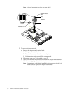
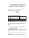
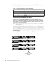
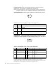
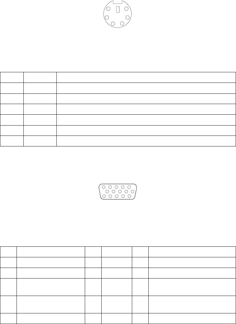
Keyboard connector: There is one keyboard connector on the end of the device
breakout cable. This connector is identified by the keyboard icon.
Note: If you attach a standard (non-USB) keyboard to the keyboard connector, the
USB ports and devices will be disabled during the power-on self-test (POST).
The following table shows the pin-number assignments for the keyboard connector
on the end of the cable.
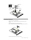
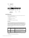
Video connector: The following table shows the pin-number assignments for the 15-
pin analog video connector on the end of the C2T device breakout cable. This cable is
not labeled but is easily identified by the dark blue 15-pin connector.
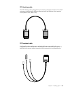
Auxiliary-device (pointing device) connector: On the end of the C2T device
breakout cable, there is one auxiliary-device connector that supports a mouse or other
pointing device. This connector is identified by the mouse icon.
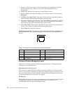
Table 12. Keyboard-connector (6-pin female) number assignments .
Pin I/O Signal
1 I/O Data
2N/AReserved
3N/AGround
4N/A+5 V dc
5I/OKeyboard clock
6N/AReserved
Table 13. Video-connector (15-pin female) number assignments.
Pin Signal Pin Signal Pin Signal
1 Red 6 Ground 11 Not connected
2 Green or monochrome 7 Ground 12 DDC SDA
3 Blue 8 Ground 13 Horizontal synchronization
(Hsync)
4Not connected 9+5 V dc
DDC
14 Vertical synchronization (Vsync)
5 Ground 10 Ground 15 DDC SCL
6
4
2
1
3
5
1
5
1115