Software Developer’s Manual 93
EEPROM Interface
EEPROM Interface 5
5.1 General Overview
The PCI/PCI-X Family of Gigabit Ethernet Controllers uses an EEPROM device for storing
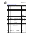
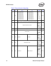
product configuration information. The EEPROM is divided into four general regions:
• Hardware accessed – loaded by the Ethernet controller after power-up, PCI Reset
deassertion, D3->D0 transition, or software commanded EEPROM reset
(CTRL_EXT.EE_RST).
• ASF accessed – loaded by the Ethernet controller in ASF mode after power-up, ASF Soft
Reset (ASF FRC_RST), or software commanded ASF EEPROM read (ASF FRC_EELD).
• Software accessed – used by software only. The meaning of these registers as listed here is a
convention for the software only and is ignored by the Ethernet controller.
• External BMC (TCO) accessed – loaded by an external BMC (TCO) from the SMBus after
power up.
Note: The 82544GC/EI and 82541ER do not support ASF, SMBus, or an external BMC (TCO).
Several words of the EEPROM are accessed automatically by the Ethernet controller after reset to
provide pre-boot configuration data before it is accessed by host software. The remainder of the
stored information is available to software for storing the MAC address, serial numbers, and
additional configuration information.
Intel has a software utility called EEUPDATE, which can be used to program EEPROM images in
development or production line environments. To obtain a copy of this program, contact your Intel
representative.
Note: Since the 82546GB/EB is a dual port device, there are portions of the EEPROM and Flash that
control one or both ports. Special considerations due to this feature are noted in this section.


