Software Developer’s Manual 95
EEPROM Interface
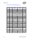
Note: These Ethernet controllers also provide identification data through the Test Access Port (TAP).
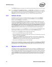
5.3 EEPROM Device and Interface
The EEPROM access algorithm, programmed into the Ethernet controller, is compatible with most,
but not all, commerically available 3.3 V dc Microwire* interfaces and serial EEPROM devices
with a 1 MHz speed rating. Ethernet controllers are compatible with two sizes of 4-wire serial
EEPROM devices
1
. If ASF mode functionality is desired, a 4096-bit serial NM93C66 compatible
EEPROM can be used. Otherwise, a 1024-bit serial NM93C46 compatible EEPROM can be used.
Both EEPROMs are accessed in 16-bit words; the larger has 256 words while the smaller has 64
words. Refer to the appropriate Ethernet controller’s design guide for recommended EEPROM
manufacturers.
An Ethernet controller automatically determines which EEPROM it is connected to and sets the
EEPROM SIZE field of the EEPROM/FLASH Control and Data Register (EEC.EE_SIZE) field
appropriately. Software can use this field to determine how to access the EEPROM using direct
access. Note that different EEPROM sizes have different numbers of address bits and therefore
must be accessed with a slightly different serial protocol. Software must be aware of this if it
accesses the EEPROM using direct access.
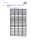
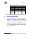
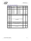
82541GI-B1 8086h 1076h Cooper
82541GI-B1 8086h 1077h Mobile
82541PI-C0 8086h 1076h Cooper
82541ER-C0 8086h 1078h Cooper
82540EP-A 8086h 1017 Desktop
82540EP-A 8086h 1016 Mobile
82540EM-A 8086h 100E Desktop
82540EM-A 8086h 1015 Mobile
Table 5-1. Component Identification
Stepping Vendor ID Device ID Description
1. The 82544GC/EI only supports one size of EEPROM. Refer to the 82544GC Gigabit Ethernet Controller Datasheet and Hardware Design
Guide (AP-427) for more information.


