Software Developer’s Manual 313
Register Descriptions
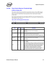
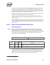
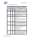
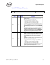
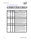
Table 13-77. TIPG Register Bit Description
31 30 29 20 19 10 9 0
Reserved IPGR2 IPGR1 IPGT
Field Bit(s)
Initial
Value
Description
IPGT 9:0 X
IPG Transmit Time
Specifies the IPG time for back-to-back packet transmissions
Measured in increments of the MAC clock:
• 8 ns MAC clock when operating @ 1 Gbps.
• 80 ns MAC clock when operating @ 100 Mbps.
• 800 ns MAC clock when operating @ 10 Mbps.
To calculate the actual IPG value for TBI applications, a value of
10 (6 for the 82544GC/EI) should be added to the IPGT value.
For the IEEE 802.3 standard IPG value of 96-bit time, the value
that should be programmed into IPGT is 10 (6 for the 82544GC/
EI).
To calculate the IPG value for 10/100/1000BASE-T applications,
a value of four should be added to the IPGT value as four clocks
are used by the MAC as internal overhead. The value that
should be programmed into IPGT is 10 (8 for the 82544GC/EI).
These values are recommended to assure that the minimum
IPG gap is met under all synchronization conditions.
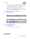
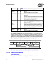
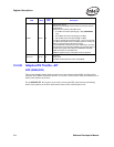
IPGR1 19:10 X
IPG Receive Time 1
Specifies the length of the first part of the IPG time for non back-
to-back transmissions. During this time, the internal IPG counter
restarts if any carrier event occurs. Once the time specified in
IPGR1 has elapsed, carrier sense does not affect the IPG
counter.
According to the IEEE802.3 standard, IPGR1 should be 2/3 of
IPGR2 value.
Measured in increments of the MAC clock:
• 8 ns MAC clock when operating @ 1 Gbps (82544GC/EI
only).
• 80 ns MAC clock when operating @ 100 Mbps
• 800 ns MAC clock when operating @ 10 Mbps.
For IEEE 802.3 minimum IPG value of 96-bit time, the value that
should be programmed into IPGR1 is eight.
IPGR1 is significant only in half-duplex mode of operation.


