Software Developer’s Manual 117
EEPROM Interface
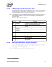
5.6.29 LED Configuration Defaults (Word 2Fh)
1
This EEPROM word specifies the hardware defaults for the LEDCTL register fields controlling the
LED0/(LINK_UP#) and LED2/LINK100 output behaviors. Refer to Table 13-60 for the LED
Control bit descriptions and Table 13-61 for the Mode Encodings.
Note: A value of 0602h is used to configure default hardware LED behavior equivalent to 82544-based
Copper adapters (LED0/LINK_UP#, LED1/ACTIVITY# (blinking), LED2/LINK100#, and
LED3/LINK1000#).
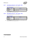
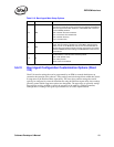
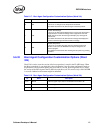
Table 5-15. LED Configuration Defaults
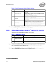
5.6.30 Boot Agent Main Setup Options (Word 30h)
The boot agent software configuration is controlled by the EEPROM with the main setup options
stored in word 30h. These options are those that can be changed by using the Control-S setup menu
or by using the IBA Intel Boot Agent utility.
Note: The 82541ER does not support the Intel Boot Agent functionality.
1. Not applicable to the 82544GC/EI.
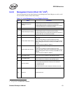
Bit Name Description
3:0 LED0 Mode
Initial value of the LED0_MODE field specifying what event/state/
pattern will be displayed on LED0 (LINK_UP) output. A value of
0010 (0x2) causes this to indicate LINK_UP state.
5:4 Reserved
Reserved.
Set as 0b.
6LED0 Invert
Initial value of LED0_IVRT field.
0b = Active-low output.
7 LED0 Blink
Initial value of LED0_BLINK field.
0b = Non-blinking.
11:8 LED2 Mode
Initial value of the LED2_MODE field specifying what event/state/
pattern will be displayed on LED2 (LINK_100) output. A value of
0110b (0x6) causes this to indicate 100 Mb/s operation.
13:12 Reserved Reserved. Set as 0b.
14 LED2 Invert
Initial value of LED2_IVRT field.
0b = Active-low output.
15 LED2 Blink
Initial value of.LED2_BLINK field.
0b = Non-blinking


