Intel
®
IXP45X and Intel
®
IXP46X Product Line of Network Processors—General Hardware
Design Considerations
Intel
®
IXP45X and Intel
®
IXP46X Product Line of Network Processors
HDD February 2007
28 Document Number: 305261; Revision: 004
3.3.7 SRAM Interface
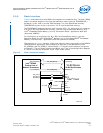
A typical connection between an 8-bit SRAM memory device and the IXP45X/IXP46X
network processors expansion bus is shown in Figure 6 on page 28. When attempting
to communicate to this device, the Timing and Control Register for Chip Select must be
configured for proper access. For more information, see the Intel
®
IXP45X and Intel
®
IXP46X Product Line of Network Processors Developer’s Manual.
.
3.3.8 Design Notes
Care must be taken when loading the bus with too many devices. As more devices are
added, the loading capacity adds up — to the point where timing can become critical.
To account for this, timing on the expansion bus may be adjusted in the Timing and
Control Register for Chip Select. If an edge rises slowly due to low drive strength, the
processors should wait an extra cycle before the value is read. For more information,
see the documentation on Timing and Control Register for Chip Select bits [29:16] in
the Intel
®
IXP45X and Intel
®
IXP46X Product Line of Network Processors Developer’s
Manual.
3.4 UART Interface
The IXP45X/IXP46X network processors provide two dedicated, Universal
Asynchronous Receiver/Transmitter Serial Ports (UARTs). These are high-speed UARTs,
capable of supporting baud rates from 1,200 Baud to 921.6 KBaud.
The hardware supports a four-wire interface:
• Transmit Data
• Receive Data
•Request to Send
•Clear to Send
Figure 6. Expansion Bus SRAM Interface
EX_ADDR[18:0]
EX_DATA[7:0]
8-Bit Device
Byte Access
CS
OE
WR
EX_ADDR[24:0]
EX_DATA[31:0]
EX_CS_N
EX_RD_N
EX_WR_N
E#
G#
W#
DATA[7:0]
ADDR[18:0]
512 Kbyte-x-8
SRAM
Interface
Intel
®
IXP46X
Product Line of
Network Processors
B4098-003


