


Intel
®
IXP45X and Intel
®
IXP46X Product Line of Network Processors
February 2007 HDD
Document Number: 305261; Revision: 004 51
General Hardware Design Considerations—Intel
®
IXP45X and Intel
®
IXP46X Product Line of
Network Processors
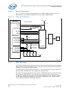
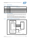
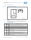
3.12.4 PCI Option Interface
The IXP45X/IXP46X network processors can be used in a design as a host or as an
option device. This section describes how the IXP45X/IXP46X network processors can
be connected as an option device to obtain proper functionality. There are slight
differences in the hardware interface when designing for option mode. All routing and
board recommendations described in previous sections of this document apply,
however the design must use the device pin connections listed in Table 21.
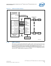
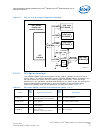
Figure 17. PCI 3.3 V to 5 V Logic Translation Interface
Intel
®
IXP46X
Product Line
Network Processor
PCI
Interface
3.3V Logic
PCI Device_ 1
3.3V Logic
PCI Device_2
3.3V Logic
PCI Device_3
5.0V Logic
PCI Device_4
OE
OE
VCC
VCC
GND
GND
5.0V
4.3V
3.3V LOGIC
5.0V LOGIC
32-Bit BUS
3.3V LOGIC
3.3V LOGIC
3.3V LOGIC
74CBT3384A
74CBT3384A
10-BIT
10-BIT
2.87K
1K
1K
B5197-01
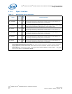
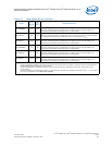
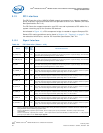
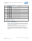
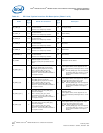
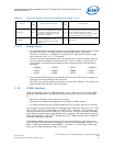
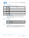
Table 21. PCI Host/Option Interface Pin Description (Sheet 1 of 3)
Name
Host
Input
Outpu
t
Device-Pin Connection
Option
Input
Outpu
t
Description
PCI_AD[31:0] I/O
All address/data signals need to be
connected between the two devices.
I/O PCI Address/Data bus
PCI_CBE_N[3:0] I/O
Connect signals to same pins between
the two devices.
I/O PCI Command/Byte Enables
PCI_PAR I/O
Connect signal to same pin between
the two devices.
I/O PCI Parity
PCI_FRAME_N I/O
Connect signal to same pin between
the two devices.
Connect a 10-KΩ pull-up resistor.
I/O PCI Cycle Frame