Intel
®
IXP45X and Intel
®
IXP46X Product Line of Network Processors
February 2007 HDD
Document Number: 305261, Revision: 004 73
PCI Interface Design Considerations—Intel
®
IXP45X and Intel
®
IXP46X Product Line of
Network Processors
6.3.1 Trace Length Limits
Maximum trace lengths can be calculated for specific speeds at which the bus is
intended to run. Typically, PCI boards with devices that can support up to 66 MHz are
designed to function at up to 66 MHz, even if the design is originally intended to run at
33 MHz. This way, if design requirements change to 66 MHz, then timing is met at the
higher frequency. In this case, the only additional requirement is to change the clock
speed and the expansion bus initial strapping at the EX_ADDR[4] signal. If you are
designing your board for 66 MHz and intend it to operate at 33 MHz, ensure that timing
equations in Section 6.2 are met at 33 MHz and 66 MHz.
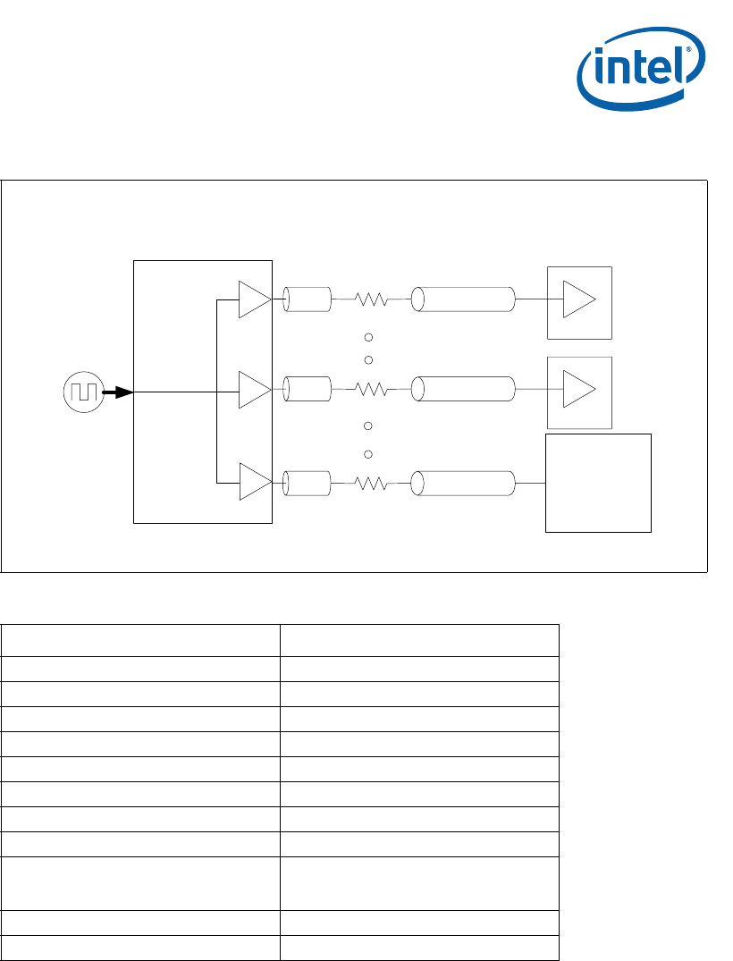
Figure 27. PCI Clock Topology
Table 26. PCI Clock Routing Guidelines
Parameter Routing Guidelines
Signal Group PCI Clock
Topology Point-to-Point
Reference Plane Ground
Characteristic Trace Impedance 55 Ω ±10%
Nominal Trace Width 5 mils
Nominal Trace Separation 10 mils
Spacing to Other Groups 20 mils
Trace length A Maximum 300 mils
Trace length B
There is no limit as long as the trace
length is maintained for each clock and
that maximum clock skew is not violated.
Resistor Rs 22 Ω ±10%
Maximum VIAS 6
A
B
PCI Devices
Rs
A
B
Rs
B4114-02
33/66 MHz
Clock
Driver
A
B
Rs
Intel
®
IXP46X
Product Line
Network
Processor


