


Intel
®
IXP45X and Intel
®
IXP46X Product Line of Network Processors—Contents
Intel
®
IXP45X and Intel
®
IXP46X Product Line of Network Processors
HDD February 2007
4 Document Number: 305261, Revision: 004
3.12.1 Signal Interface......................................................................................48
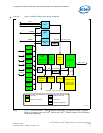
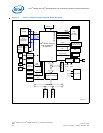
3.12.2 PCI Interface Block Diagram.....................................................................49
3.12.3 Supporting 5 V PCI Interface....................................................................50
3.12.4 PCI Option Interface................................................................................51
3.12.5 Design Notes..........................................................................................53
3.13 JTAG Interface ..................................................................................................53
3.13.1 Signal Interface......................................................................................54
3.14 Input System Clock............................................................................................54
3.14.1 Clock Signals .........................................................................................54
3.14.2 Clock Oscillator.......................................................................................54
3.14.3 Device Connection ..................................................................................55
3.15 Power ..............................................................................................................55
3.15.1 De-Coupling Capacitance Recommendations...............................................56
3.15.2 VCC De-Coupling ....................................................................................56
3.15.3 VCCP De-Coupling ..................................................................................56
3.15.4 VCCM De-Coupling..................................................................................56
3.15.5 Power Sequence .....................................................................................56
3.15.6 Reset Timing..........................................................................................56
4.0 General PCB Guide ...................................................................................................59
4.1 PCB Overview ...................................................................................................59
4.2 General Recommendations..................................................................................59
4.3 Component Selection .........................................................................................59
4.4 Component Placement........................................................................................59
4.5 Stack-Up Selection.............................................................................................60
5.0 General Layout and Routing Guide ...........................................................................63
5.1 Overview..........................................................................................................63
5.2 General Layout Guidelines...................................................................................63
5.2.1 General Component Spacing ....................................................................64
5.2.2 Clock Signal Considerations......................................................................66
5.2.3 SMII Signal Considerations ......................................................................67
5.2.4 MII Signal Considerations ........................................................................67
5.2.5 USB Considerations.................................................................................67
5.2.6 Cross-Talk .............................................................................................68
5.2.7 EMI-Design Considerations.......................................................................68
5.2.8 Trace Impedance....................................................................................69
5.2.9 Power and Ground Plane..........................................................................69
6.0 PCI Interface Design Considerations.......................................................................71
6.1 Electrical Interface.............................................................................................71
6.2 Topology ..........................................................................................................71
6.3 Clock Distribution ..............................................................................................72
6.3.1 Trace Length Limits.................................................................................73
6.3.2 Routing Guidelines..................................................................................74
6.3.3 Signal Loading........................................................................................74
7.0 DDR-SDRAM.............................................................................................................75
7.1 Introduction......................................................................................................75
7.1.1 Selecting VTT Power Supply .....................................................................80
7.1.2 Signal-Timing Analysis ............................................................................81
7.1.3 Printed Circuit Board Layer Stackup ..........................................................84
7.1.4 Printed Circuit Board Controlled Impedance................................................85
7.1.5 Timing Relationships ...............................................................................87
7.1.6 Resistive Compensation Register (Rcomp)..................................................88
7.1.7 Routing Guidelines..................................................................................88