


Intel
®
IXP45X and Intel
®
IXP46X Product Line of Network Processors
February 2007 HDD
Document Number: 305261; Revision: 004 29
General Hardware Design Considerations—Intel
®
IXP45X and Intel
®
IXP46X Product Line of
Network Processors
Note: The UART module does not support full modem functionality. However, this can be
implemented, by using GPIO ports to generate DTR, DSR, RI, and DCD and making
some changes to the driver.
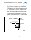
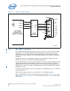
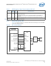
3.4.1 Signal Interface
The following figure contain a typical four signal interface between the UART and an
RS-232 transceiver driver, required to interface with external devices. Unused inputs to
the RS-232 driver can be connected to ground. This avoids signals floating to
undetermined states which can cause over heating of the driver leading to permanent
damage.
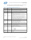
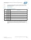
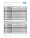
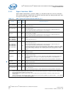
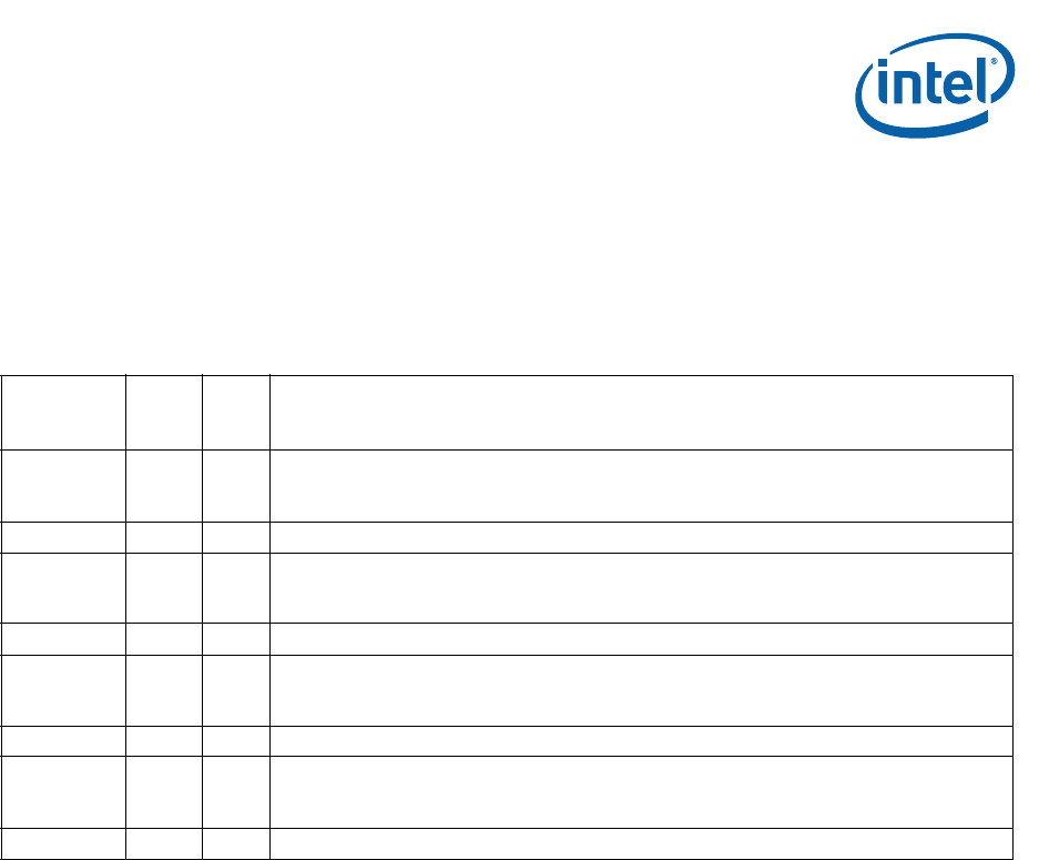
Table 7. UART Signal Recommendations
Name
Input
Output
Pull
Up
Down
Recommendations
RXDATA0 I Yes
Serial data input Port 0.
When signal is not being used in the system, this pin should be pulled high with a 10-KΩ
resistor.
TXDATA0 O No Serial data output Port 0.
CTS0_N I Yes
Clear-To-Send Port 0.
\When signal is not being used in the system, this pin should be pulled high with a 10-KΩ
resistor.
RTS0_N O No Request-To-Send Port 0.
RXDATA1 I Yes
Serial data input Port 1.
When signal is not being used in the system, this pin should be pulled high with a 10-KΩ
resistor.
TXDATA1 O No Serial data output Port 1.
CTS1_N I Yes
Clear-To-Send Port 1.
When signal is not being used in the system, this pin should be pulled high with a 10-KΩ
resistor.
RTS1_N O No Request-To-Send Port 1.