


Intel
®
IXP45X and Intel
®
IXP46X Product Line of Network Processors—Category
Intel
®
IXP45X and Intel
®
IXP46X Product Line of Network Processors
HDD February 2007
60 Document Number: 305261; Revsion: 004
• Place noisy parts (clock, processor, video, etc.) at least 1.5 – 3 inches away from
the edge of the printed circuit board.
• Do not place noisy components close to internal/external cables
— Any loose cables picks up noise and act as an antenna to radiate that noise
— Be aware of the peak in-rush surge current into the device pins. This surge
current may inject high-frequency switching noise into power planes of the
printed circuit board.
• Place high-current components near the power sources.
• Do not share the same physical components (such as buffers and inverters)
between high-speed and low-speed signals. Use separate parts.
• Place clock drivers and receivers such that clock trace length is minimized.
• Place clock generation circuits near a ground stitch location. Place a localized
ground plane around the clock circuits and connect the localized plane to system
ground plane.
• Install clock circuits directly on the printed circuit board, not on sockets.
• Clock crystals should lie flat against the board to provide better coupling of
electromagnetic fields to the board.
4.5 Stack-Up Selection
Stack-up selection directly affects the trace geometry which, in turn, affects the
characteristic impedance requirement for the printed-circuit board. Additionally, the
“clean,” noise-free-planes design and placement is significantly important as
components run at higher speeds requiring more power.
Considerations include:
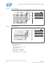
• Low-speed, printed-circuit-board construction — for example two-layer boards:
— Advantages:
•Inexpensive
• Manufactured by virtually all printed-circuit-board vendors
— Disadvantages:
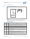
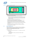
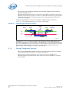
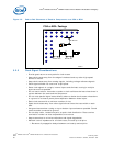
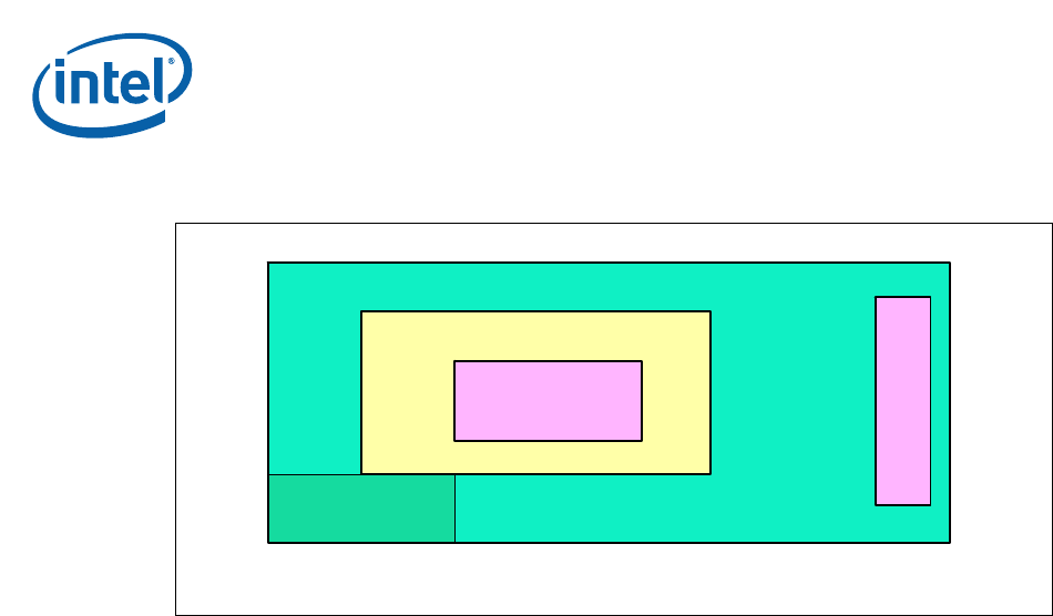
Figure 19. Component Placement on a PCB
B2264-01
PCB
High Frequency
Components
Medium Frequency
Low FrequencyAnalog Circuit
C
O
N
N
E
C
T
O
R