


Intel
®
IXP45X and Intel
®
IXP46X Product Line of Network Processors—General Hardware
Design Considerations
Intel
®
IXP45X and Intel
®
IXP46X Product Line of Network Processors
HDD February 2007
34 Document Number: 305261; Revision: 004
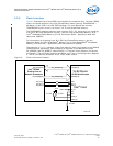
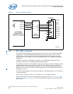
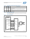
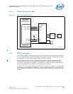
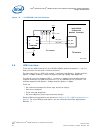
3.5.3 Signal Interface, SMII
Serial Media Independent Interface (SMII) is a hardware feature to convey complete
MII interface between a MAC and 10/100 PHY interface with two data pins per port and
one synchronizing signal for multi PHYs.
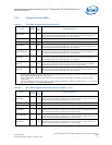
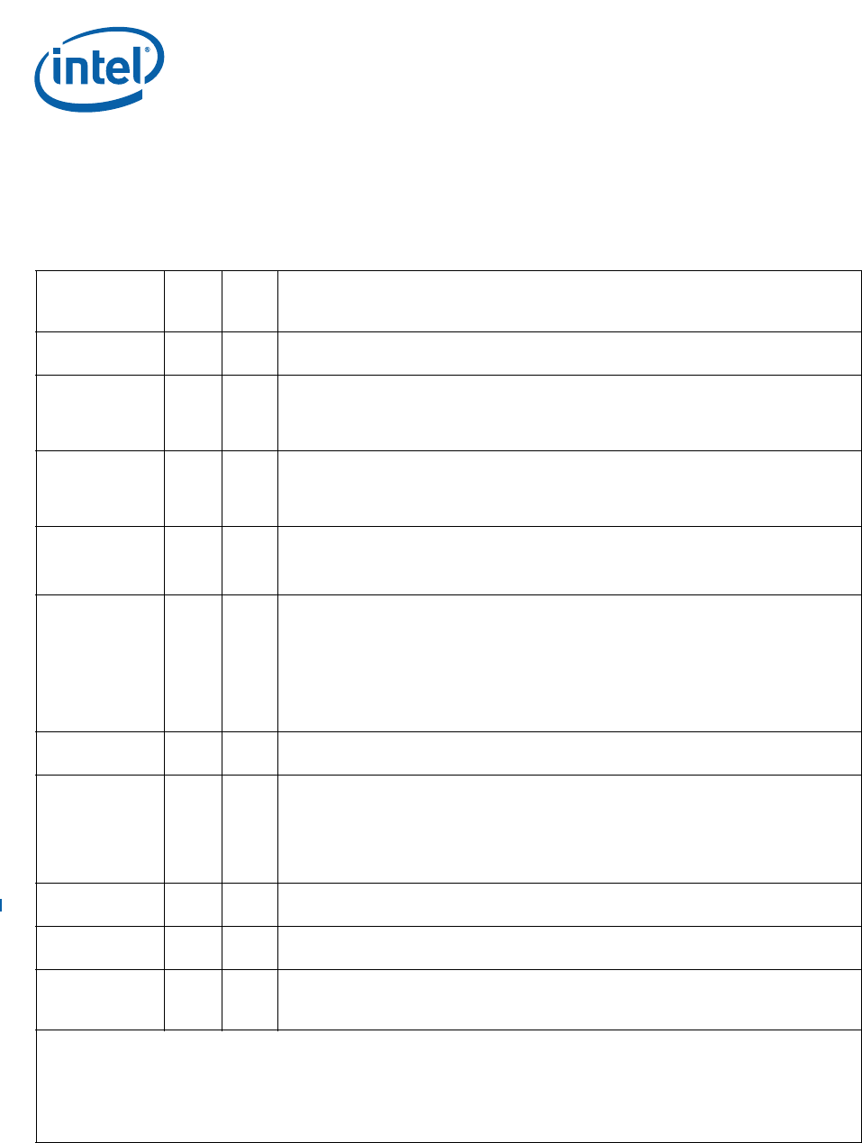
Table 12. SMII Signal Recommendations: NPE A, B, C
Name
Input/
Output
Pull
Up/
Down
Recommendations
SMII_TXDATA[4] O No
NPE A
Transmit Data Port 4.
SMII_RXDATA[4] I Yes
NPE A
Received Data Port 4.
When this interface/signal is enabled and is not being used in a system design, the
interface/signal should be pulled high with a 10-KΩ resistor.
SMII_CLK I Yes
NPE A,B,C
Reference Clock, 125-MHz.
When this interface/signal is enabled and is not being used in a system design, the
interface/signal should be pulled high with a 10-KΩ resistor.
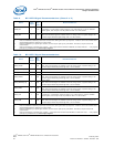
SMII_TXDATA[0] /
SMII_TXDATA[1] /
SMII_TXDATA[2] /
SMII_TXDATA[3]
ONo
NPE B
Transmit Data Ports 3,2,1,0.
SMII_RXDATA[0] /
SMII_RXDATA[1] /
SMII_RXDATA[2] /
SMII_RXDATA[3]
IYes
NPE B
Transmit Data Ports 3,2,1,0.
When this interface/signal is enabled and is not being used in a system design, the
interface/signal should be pulled high with a 10-KΩ resistor.
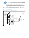
One special configuration exists for the board designer. When NPE B is configured in SMII
mode of operation and a subset of the four SMII ports are utilized (i.e. All four are enabled
but only two are being connected). The unused inputs must be tied high with a 10-KΩ
resistor.
SMII_SYNC O No
NPE B
Synchronous pulse.
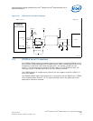
ETH_MDIO I/O Yes
NPE A,B,C
Management data output.
An external pull-up resistor of 1.5 KΩ is required on ETH_MDIO to properly quantify the
external PHYs used in the system. For specific implementation, see the IEEE 802.3
specification.
Should be pulled high through a 10-KΩ resistor when not being utilized in the system.
ETH_MDC I/O No
NPE A,B,C
Management data clock.
SMII_TXDATA[5] O No
NPE C
Transmit Data Ports 5.
SMII_RXDATA[5] I Yes
NPE C
Receive Data Ports 5.
Should be pulled high through a 10-KΩ resistor when not being utilized in the system.
Notes:
1. Features disabled/enabled by Soft Fuse must be done during the boot-up sequence. A feature cannot be enabled after
being disabled without asserting a system reset.
2. Features disabled by a specific part number, do not require pull-ups or pull-downs. Therefore, all pins can be left
unconnected.
3. Features enabled by a specific part number — and required to be Soft Fuse-disabled, as stated in Note 1 — only require
pull-ups or pull-downs in the clock-input signals.