


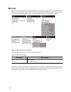

79
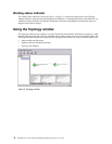
Fibre Channel switch module and link status
The Fibre Channel switch module icon shape and color provide information about the switch and its
operational state. In the Topology window, lines represent links between switch modules. See Table 16 for
Fibre Channel switch module and link status and “Fabric status” on page 86 for more information about other
Topology window icons.
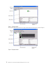
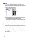
Working with switch modules and links
Switch module and link icons are selectable and moveable and serve as access points for other windows and
menus. You select switch modules and links to display information, modify configurations, or delete them
from the window. The context-sensitive pop-up menus are accessible through the switch module and link
icons.
Click a switch module or link in the graphic window to display its status in the data window. To select multiple
switch modules or links, hold down the Ctrl key while selecting. When no switch modules or links are
selected, information about all switch modules is displayed. To deselect a switch module or link that is
currently selected, click the switch or link.
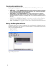
Different switch module icons will be displayed depending on the different switch vendor products present in
the attached fabric. See Table 17 on page 87 for a list of switch module icons and vendors. Attached switch
modules that are not manageable through the SAN Utility will be displayed as “third-party manageable”
switch icons. The topology configuration in Figure 6 on page 80 shows an example of a switch fabric with
third-party switch modules.
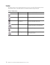
Table 16. Fibre Channel switch module and link status indicators
Switch module icon color Status
Green Normal Fibre Channel switch operation
Amber Operational with errors
Red Inactive or Fibre Channel switch failure
Blue Unknown Fibre Channel device