


Contents
xii
Extent of Limited Warranty....................................................................................................85
Warranty Limitations and Exclusions ....................................................................................86
Limitations of Liability ...................................................................................................86
How to Obtain Warranty Service...........................................................................................87
Telephone Support.......................................................................................................87
Returning a Defective Product .....................................................................................87
Figures
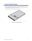
Figure 1. Intel
®
Server Chassis SR1450 ....................................................................................14
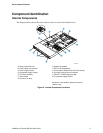
Figure 2. Internal Component Locations....................................................................................17
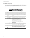
Figure 3. Standard Control Panel Features ...............................................................................18
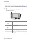
Figure 4. Intel
®
Local Control Panel Features ............................................................................20
Figure 5. Chassis Back..............................................................................................................20
Figure 6. Optional Peripherals ...................................................................................................21
Figure 7. Removing the Chassis Cover .....................................................................................25
Figure 8. Installing the Chassis Cover .......................................................................................26
Figure 9. Standard Front Bezel..................................................................................................27
Figure 10. Intel
®
Local Control Panel Front Bezel......................................................................27
Figure 11. Removing the Front Bezel ........................................................................................27
Figure 12. Installing the Front Bezel ..........................................................................................28
Figure 13. Removing the Processor Air Duct.............................................................................29
Figure 14. Preparing the Processor Air Duct .............................................................................30
Figure 15. Installing the Processor Air Duct...............................................................................30
Figure 16. Removing a Hot-swap Hard Drive Carrier from Chassis ..........................................31
Figure 17. Removing the Baffle from a Hot-swap Drive Carrier.................................................32
Figure 18. Attaching a Hot-swap Hard Disk Drive to a Carrier...................................................32
Figure 19. Inserting a Hot-swap Hard Disk Drive Assembly into the Chassis............................33
Figure 20. Installing a Floppy Drive into the Slimline Carrier.....................................................34
Figure 21. Installing Floppy Flat Flex Cable to a Floppy Drive ..................................................35
Figure 22. Installing the Floppy Drive Interposer Board.............................................................35
Figure 23. Installing the Slimline Floppy Drive into the Chassis ................................................36
Figure 24. Removing the Rails from the Floppy Drive Conversion Kit Carrier...........................37
Figure 25. Inserting a Drive into the Floppy Conversion Kit Carrier...........................................38
Figure 26. Attaching a Drive to Floppy Drive Conversion Kit Carrier.........................................38
Figure 27. Install the Rails onto the Floppy Drive Conversion Kit Carrier..................................39
Figure 28. Installing the Flat Flex Cable to the Floppy Drive .....................................................39
Figure 29. Installing a DVD-ROM / CD-ROM Drive into the Carrier...........................................41
Figure 30. Installing a DVD/CDROM Drive into the Chassis .....................................................42
Figure 31. Removing the PCI Riser Assembly from the Chassis...............................................44
Figure 32. Installing an Add-in Card into the PCI Riser Assembly.............................................45
Figure 33. Installing the PCI Riser Assembly into the Chassis..................................................45
Figure 34. Removing the PCI Riser Assembly from the Chassis...............................................47
Figure 35. Installing an Add-in Card to the PCI Riser Assembly................................................48
Figure 36. Installing the PCI Riser Assembly into the Chassis..................................................48
Figure 37. Removing the Standard Control Panel from the Chassis .........................................50
Figure 38. Removing the Intel
®
Local Control Panel from the Chassis ......................................51
Figure 39. Removing a System Fan Module..............................................................................53
Figure 40. Removing the Single System PCI Fan .....................................................................55