


Server Chassis Features
18
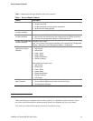
Standard Control Panel
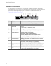
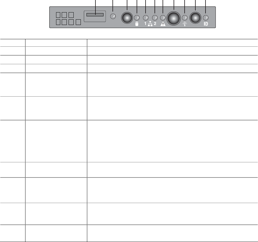
The diagram below shows the features available on the Standard Control Panel. The Standard
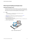
Control Panel is one of two required front panel options that can be selected. The other option is the
Intel® Local Control Panel. For instructions on installing the Standard Control Panel, see
“Replacing the Standard Control Panel.”
TP01586
A CB
D
F G KIH J
E
Callout Feature Function
A USB 2.0 port Allows you to attach a USB component to the front of the chassis.
B NMI button Puts the server in a halt-state for diagnostic purposes.
C Reset button Reboots and initializes the system.
D Hard disk drive
activity LED
Random blinking green light indicates hard disk drive activity (SCSI
or SATA).
No light indicates no hard disk drive activity.
E
F
NIC 1 activity LED
NIC 2 activity LED
Blinking green light indicates network activity.
Continuous green light indicates a link between the system and the
network to which it is connected.
G System Status LED Solid green indicates normal operation
Blinking green indicates degraded performance
Solid amber indicates a critical or non-recoverable condition
Blinking amber indicates a non-critical condition
No light indicates POST is running or the system is off
H Power/Sleep button Toggles the system power on/off. Sleep button for ACPI-compatible
operating systems.
I Power/Sleep LED Continuous green light indicates the system has power applied to it.
Blinking green indicates the system is in S1 sleep state
No light indicates the power is off / is in ACPI S4 or S5 state.
J System identification
button
Toggles the front panel ID LED and the server board ID LED on and
off. The server board LED is visible from the rear of the chassis and
allows you to locate the server from the rear of a rack of systems.
K System Identification
LED
Solid or blinking blue indicates system identification is active
No light indicates system identification is not activated
Figure 3. Standard Control Panel Features