


Server Chassis Features
20
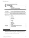
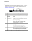
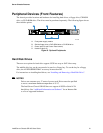
Callout Feature Function
J System Status LED Solid green indicates normal operation.
Blinking green indicates degraded performance.
Solid amber indicates a critical or non-recoverable condition.
Blinking amber indicates a non-critical condition.
No light indicates POST is running or the system is off.
K
L
NIC 2 activity LED
NIC 1 activity LED
Continuous green light indicates a link between the system and the
network to which it is connected.
Blinking green light indicates network activity.
M Hard disk drive
activity LED
Random blinking green light indicates hard disk drive activity (SCSI
or SATA).
No light indicates no hard disk drive activity is taking place.
N Reset button Reboots and initializes the system.
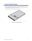
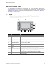
Figure 4. Intel
®
Local Control Panel Features
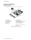
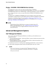
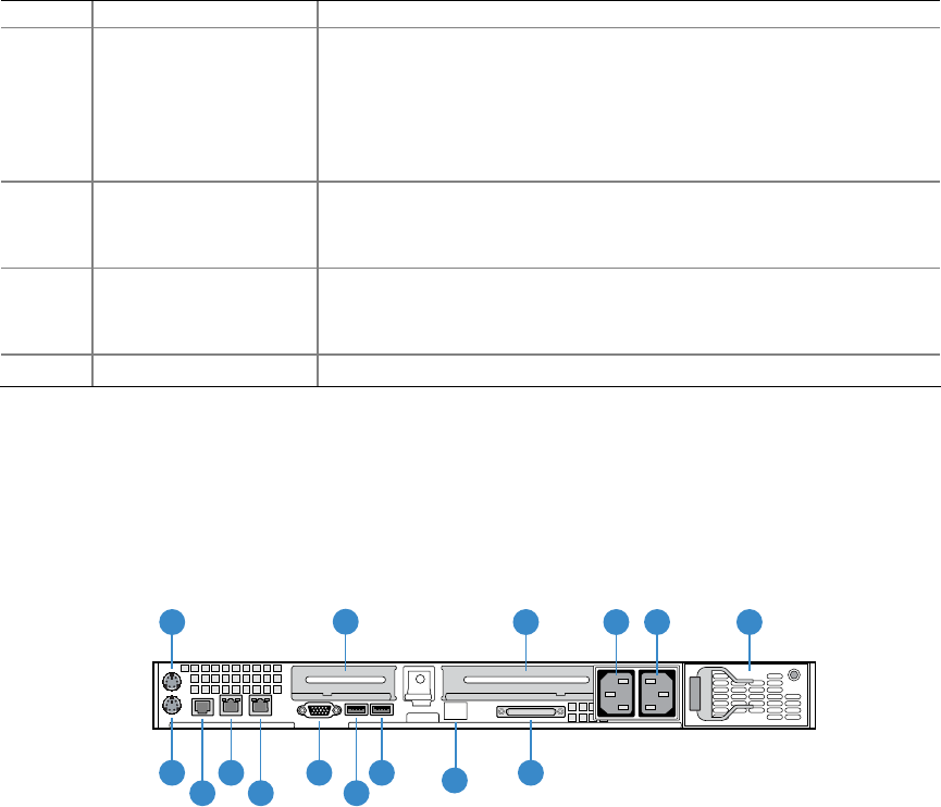
Back Panel Features
TP01588
A
B
I
H
G K
L
M O
J
C ED
F
N
A. Mouse port I. NIC1
B. Low-profile add-in card bracket J. NIC2
C. Full-height add-in card bracket K. Video
D. AC power receptacle (front power supply) L. USB1
E. AC power receptacle (rear power supply) M. USB0
F. Rear power supply module
N. IMM Advanced Dedicated NIC
Knock Out
G. Keyboard port O. SCSI Channel B
H. Serial Port B
Figure 5. Chassis Back
✏ NOTE
The AC power supply receptacles are linked to separate power supply
modules.