


Hardware Installations and Upgrades
40
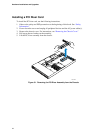
14. Attach the other end of the flat flex cable to the interposer board.
15. Install the interposer board into the floppy drive conversion kit carrier. One screw attaches on
the right side.
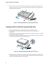
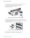
16. Slide the carrier assembly into center hard drive bay until it clicks into place.
17. Attach the power and data cables to the interposer board.
18. Attach the other end of the power and data cables to the server board.
19. Install the chassis cover. For instructions, see “Installing the Chassis Cover.”
20. (Optional) Install the front bezel. For instructions, see “Removing and Installing the Front
Bezel.”
21. Plug all peripheral devices and the AC power cable(s) back into the server.
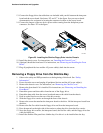
Removing a Floppy Drive from the Converted Hard Drive Bay
1. Observe the safety and ESD precautions at the beginning of this book. See “Safety
Information.”
2. Power down the server and unplug all peripheral devices and the AC power cable(s).
3. Remove the chassis cover. For instructions, see “Removing the Chassis Cover.”
4. Remove the front bezel if it is installed. For instructions, see “Removing and Installing the
Front Bezel.”
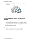
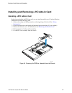
5. Remove cables from the interposer board.
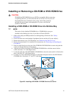
6. Push in on the lever at the rear of the floppy carrier and slide the drive from the front of the
chassis.
7. Remove the interposer board.
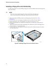
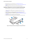
8. Remove the flat flex cable from the interposer board.
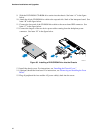
9. Open the connector cover on the rear of the floppy drive by pulling up on it. Release the flat
flex cable from the drive.
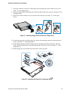
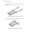
10. Remove the two screws at each side that hold the drive rails to the drive carrier. Lift the two
rails from the carrier.
11. Remove the two screws attaching the drive to the converted hard drive bay carrier.
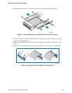
12. Install an empty hot-swap hard drive carrier into chassis drive bay if no floppy or hard drive is
to be installed into the bay.
13. Store the screws, the converted drive bay carrier, the side rails, interposer board, floppy cable
and the flat flex cable for future use.
14. Install the chassis cover. For instructions, see “Installing the Chassis Cover.”
15. (Optional) Install the front bezel. For instructions, see “Removing and Installing the Front
Bezel.”
16. Plug all peripheral devices and the AC power cable(s) back into the server.