


DLA-G150CLU
DLA-G150CLE
1-5
No.51931
9
Controls and Features
ENGLISHDEUTSHFRANÇAISITALIANOESPAÑOL
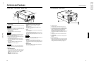
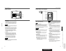
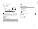
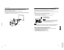
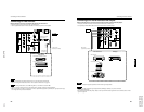
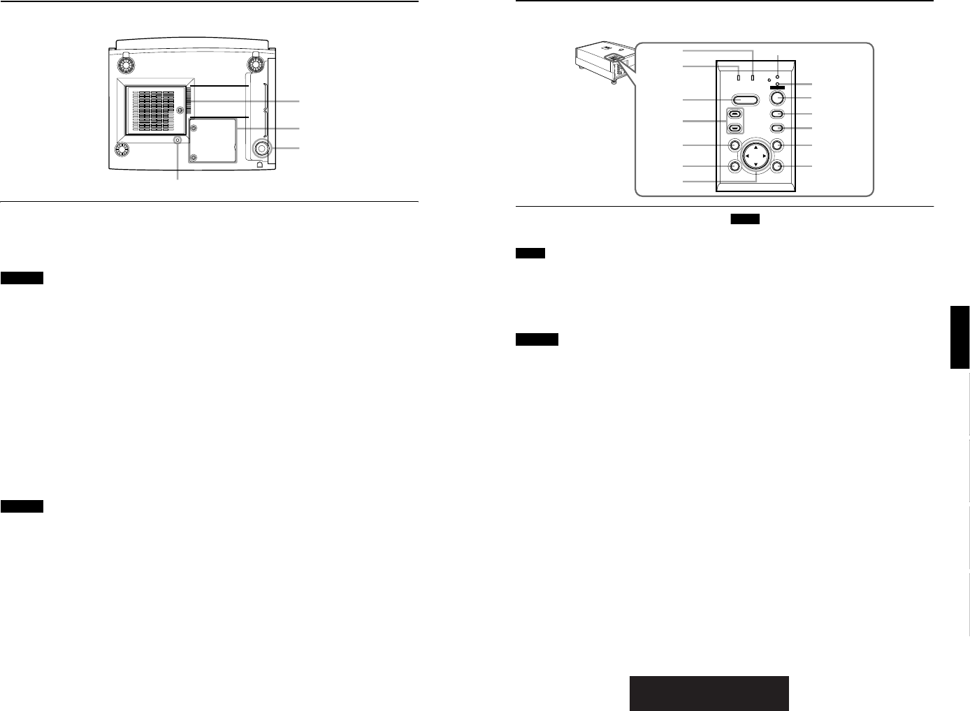
Control Panel on the Projector
1 STAND BY Indicator
ON : When in stand-by mode.
Blinking :When in cool-down mode.
Memo
About the cool-down mode:
This projector has a function to cool down the heated lamp for a
fixed period of time (approx. 120 seconds) after projection is
finished. This feature is referred to as the cool-down mode.
The purpose of the cool-down mode is to prevent inner parts
from being deformed or broken by heat from the heated lamp
as well as to prolong the life of the lamp.
CAUTIONS
• Do not turn off the MAIN POWER switch while in the cool-
down mode.
• Do not place the projector on its side or stand it upright
while in the cool-down mode; this may block the vents.
2 OPERATE indicator
ON : When the projector is in operation (projecting).
OFF : When the projector is not in operation (not
projecting).
3
OPERATE button
When the projector is in the stand-by mode, press this
button one second or more, and the projector is turned
on, causing the OPERATE indicator to light.
Press it one second or more again, and the projector
goes into the cool-down mode, then stand-by mode.
(Refer to page 32.)
* You cannot use the OPERATE button for about one
minute after the lamp blinks. Press the button after a
minute or longer has elapsed.
Memo
While in the cool-down mode (STAND BY indicator is blinking):
Even if you press the OPERATE button, the projector is not
turned on. Wait until the projector enters stand-by mode
(STAND BY indicator stays lit).
4 PC button
Use this button to select a device connected to the PC 1,
PC 2 or DVI terminals. Each time you press the button,
the selection alternates among PC 1, PC 2 and DVI.
* “PC1” , “PC2” or “DVI” will be displayed on the top right of
the projected image. (This function can be disabled by
the menu.)
5 VIDEO button
Use this button to select a device such as a video deck
connected to the AV IN (Y/C, VIDEO or COMP) terminal
of the projector. Each time you press the button, the
selection alternates among Y/C, VIDEO and COMP.
* “Y/C”, “VIDEO” or “COMP” will be displayed on the top right of
the projected image. (This function can be disabled by the
menu.)
6
MENU button
Use this button to enter or exit the menu mode. The main
menu appears or disappears at the screen. For details,
refer to “Basic Menu Operation” on page 43.
7 ENTER button
This button will be used in the menu mode. Use to
display the hierarchical menus. Also use when “ENTER”
is displayed against the item on the menu screen or
when the “All reset” selection is confirmed. For details,
refer to “Basic Menu Operation” on page 43.
8
Cursor buttons
5
/
∞
/
2
/
3
These buttons will be used in the menu mode to select an
item, or to set or adjust the value. For details, refer to
“Basic Menu Operation” on page 43.
V
I
D
E
O
P
C
L
A
M
P
T
E
M
P
S
T
A
N
D
B
Y
M
E
N
U
K
E
Y
S
T
O
N
E
P
R
E
S
E
T
E
X
I
T
E
N
T
E
R
O
P
E
R
A
T
E
H
I
D
E
D
O
W
N
U
P
3
4
5
6
7
2
1
r
w
q
p
9
8
e
LAMP TEMP
STAND BY
HIDE
PC
VIDEO
MENU
KEYSTONE
PRESET
EXIT ENTER
OPERATE
8
Controls and Features
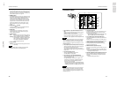
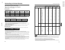
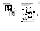
Bottom Surface
t Air inlet (filter)
Air is taken in through the filter to cool the light-source
lamp. If the filter is blocked or if something that obstructs
the flow of air is placed around the projector, heat may
build up inside and could cause a fire. For required
space, refer to “Precautions for Installation” on page 15.
CAUTIONS
• Be careful as paper, cloth or soft cushion could be drawn in
if placed nearby. Do not block the filter, or heat may build
up and could cause a fire.
• Clean the filter periodically. For details, refer to “Cleaning
and Replacing the Filter Cover” on page 63. Deposition of
dirt on the filter reduces the cooling effect, causing heat to
build up inside, which could cause a fire or malfunction.
y
Opening for replacing the light-source lamp
For replacing the light-source lamp, refer to “Replacing
the Light-Source Lamp” on page 58.
u Fixing foot
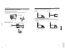
i Position selecting screw for ceiling mounting
When using the projector in an upside-down, ceiling-
mounted position (inverted top-to-bottom and right-to-
left), the “position selecting screw for ceiling mounting”
must be turned to switch to ceiling mounting.
This will correct variance in color images (shading),
which otherwise would occur in ceiling mounting.
For more information, refer to “Setting the Position
Selecting Screw for Ceiling Mounting” on page 21.
CAUTION
• To ceiling-mount and adjust the projector, special expertise
and technique are necessary. Be sure to ask your dealer or
specialist to perform this work.
u
y
t
i
DLA-G150CLU