


DLA-G150CLU
DLA-G150CLE
1-78
No.51931
74
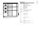
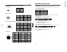
RS-232C external control
By connecting a computer to the RS-232C terminal, you can control the projector. Use a reverse connection cable as the RS-
232C connection cable.
The commands to control the projector and the response data against the received commands are explained here.
For further information, please consult the dealer where you purchased your projector or consult the Service Center.
1. Communication Specifications
The communication specifications are as follows:
* Factory set value. To change the value, refer to “Setting and Adjusting Other Functions (OPTIONS)” on page 54.
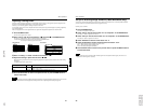
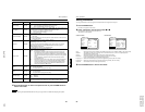
2. Command Format
2-1. Command data format (from the computer to the projector)
When sending a control command, use the following data format.
Header: Designates the head of data and the kind of data.
“!” (21h): Control command to the projector
“?” (3Fh): Query to the projector (Asking command)
ID: “1” (fixed)
SP: Designates the delimiter for ID, Command, and Parameter. (20h)
CR: Designates the terminal of the data. (0Dh)
* [ ] is not necessary when Asking command.
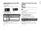
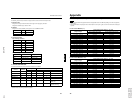
2-2. Response data format (from the projector to the computer)
Upon executing the received control command, the projector sends back the following response data to the computer.
Header: Designates the head of data.
“@” (40h): Fetches data from the projector.
ID: “1” (fixed)
SP: Designates the delimiter for ID, Command, and Parameter (20h)
Normal Termination Status: “0” (30h)
CR: Designates the terminal of the data (0Dh)
Baud rate 9600bps / 19200bps*
Data length 8 bits
Parity None
Stop bit 1 bit
Flow control None
Header ID SP Command SP Parameter CR
Header ID SP Normal Termination Status SP Parameter CR
73
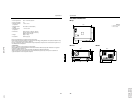
Specifications
ENGLISHDEUTSHFRANÇAISITALIANOESPAÑOL
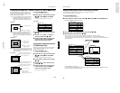
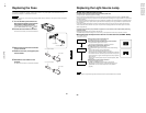
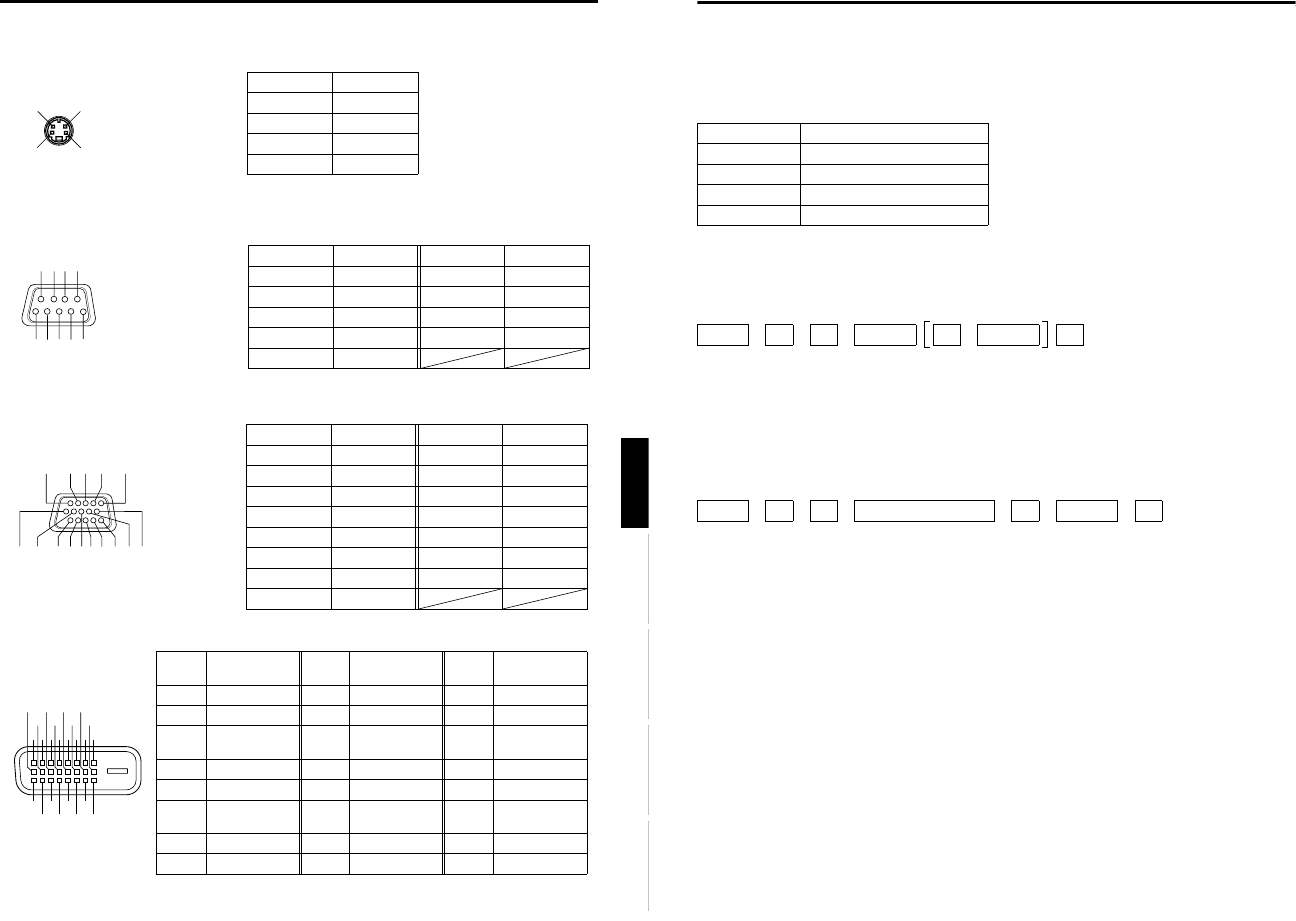
Pin assignment (Specifications for terminals)
■ Y/C terminal
■ RS-232C terminal
■ PC1 terminal/PC OUT terminal
■ DVI terminal
1
2
34
Pin number Signal name
1GND (Y)
2 GND (C)
3Y
4C
2
3
4
5
6
7
1
89
Pin number Signal name Pin number Signal name
1N/C6N/C
2RD7N/C
3 TD8N/C
4N/C9N/C
5GND
1
2
3
4
5
6
7
8910
11
12
13
14
15
Pin number Signal name Pin number Signal name
1Red9N/C
2 Green 10 GND (SYNC)
3Blue11GND
4N/C12N/C
5N/C13H.SYNC
6 GND (Red) 14 V.SYNC
7 GND (Green) 15 N/C
8 GND (Blue)
12345678
17
9111315
10 12 14 16
18
19
20
21
22
23
24
Pin
number
Signal name
Pin
number
Signal name
Pin
number
Signal name
1 T.M.D.S.Data2- 9 T.M.D.S.Data1- 17 T.M.D.S.Data0-
2 T.M.D.S.Data2+ 10 T.M.D.S.Data1+ 18 T.M.D.S.Data0+
3
T.M.D.S.Data2
Shield
11
T.M.D.S.Data1
Shield
19 T.M.D.S.Data0
Shield
4 No Connect 12 No Connect 20 No Connect
5 No Connect 13 No Connect 21 No Connect
6 DDC Clock 14 +5V Power 22 T.M.D.S. Clock
Shield
7 DDC Data 15 Ground (for +5 V) 23 T.M.D.S. Clock +
8 No Connect 16 Hot Plug Detect 24 T.M.D.S. Clock -