


DLA-G150CLU
DLA-G150CLE
1-6
No.51931
11
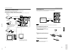
Controls and Features
ENGLISHDEUTSHFRANÇAISITALIANOESPAÑOL
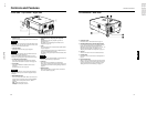
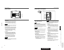
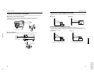
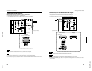
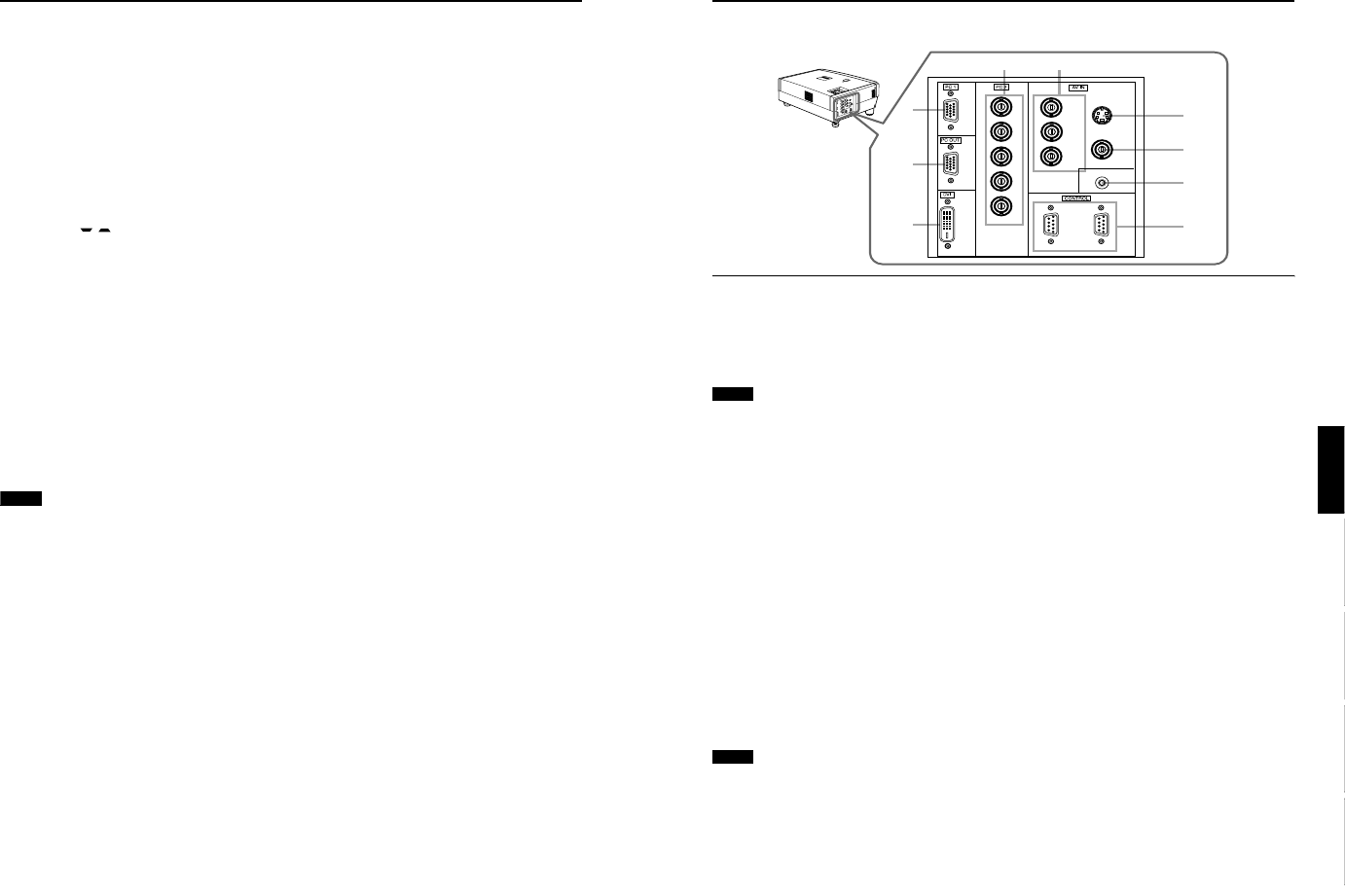
Connector Panel
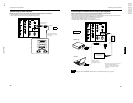
1 PC (computer) 1 input terminal (D-sub 3-row 15
pin)
This is an input terminal dedicated to computer signals
(RGB video signals and sync signals).
Connect the display output terminal of the computer to
this terminal. When a Macintosh computer is to be
connected, use the supplied conversion adapter for Mac.
Note
• When computer-related signals are input, the uppermost
edge of the image may appear to bow if the sync signal
input is composite sync (Cs) or G on sync signal. In this
case, use separate sync signals for vertical sync (V) and
horizontal sync (H).
2 PC (computer) OUT terminal (D-sub 3-row 15 pin)
This is the terminal for video output from the monitor of
the computer connected to PC1 or PC2.
The computer input signal projected on the screen is
output. A display monitor can be used by connecting it to
this terminal.
3 DVI terminal [DVI-D 24 pin]
This is the digital RGBHV input terminal.
• The Mac ADC is not supported.
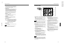
4 PC (computer) 2 input terminals (BNC ×
××
×
5)
These are multipurpose video input terminals that allow
input of the following signals.
• Analog RGB signals, vertical sync (V) signals, and
horizontal sync (H) signals / composite signals (Cs).
(Devices which have analog RGB signal output
terminals can be connected.)
* Input of external sync signals is automatically detected.
Detection of H/V signals or Cs signals causes automatic
switching to external sync. The priority order is H/V > Cs.
Note
• When computer-related signals are input, the uppermost
edge of the image may appear to bow if the sync signal
input is composite sync (Cs) or G on sync signal. In this
case, use separate sync signals for vertical sync (V) and
horizontal sync (H).
5 Component terminal
Component signals (Y, B-Y, R-Y) or DTV-format (Y, P
B
,
P
R
) signals. (Devices which have component output
terminals can be connected.)
* For details about DTV-format signals (480i, 480p, 720p,
1080i) compatible with this unit, refer to page 22.
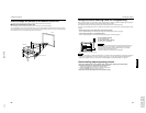
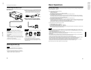
6 Y/C (S-video) input terminal (Mini DIN 4 pin)
Connect this terminal to the S-video output terminal of a
video deck, etc.
Attach the ferrite core (accessory) to the cable which is
connected to the Y/C input terminal. (Refer to page 29.)
7
VIDEO (composite video) input terminal (BNC)
Connect this terminal to the composite video output
terminal of a video deck, etc.
8
REMOTE terminal (stereo mini jack)
Connect an infrared remote control extension unit, etc. to
this jack.
Attach the ferrite core (accessory) to the cable which is
connected to the REMOTE terminal. (Refer to page 29.)
* For details, consult your dealer.
9 RS-232C CONTROL terminal IN/OUT (D-sub 9 pin)
This is the RS-232C interface-specified terminal. The
projector can be controlled by a computer connected
externally.
* For details, refer to page 27 and 74.
2
3
1
54
7
8
9
6
V
I
D
E
O
P
C
L
A
M
P
T
E
M
P
S
T
A
N
D
B
Y
M
E
N
U
K
E
Y
S
T
O
N
E
P
R
E
S
E
T
E
X
I
T
E
N
T
E
R
O
P
E
R
A
T
E
H
I
D
E
D
O
W
N
U
P
Y
P
B
/B-Y
P
R
/R-Y
IN
REMOTE
Y/C
VIDEO
R
G
B
H
IN OUT
V
10
Controls and Features
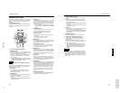
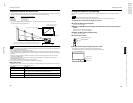
9 EXIT button
This button will be used in the menu mode to return to the
previous menu. When the main menu is displayed, this
button will cause the menu to disappear. For details, refer
to “Basic Menu Operation” on page 43.
p PRESET button
This PRESET button only works as a reset button for the
direct button adjustment of the KEYSTONE button of the
control panel and the DIGITAL ZOOM button of the
remote control. When adjusting the keystone or digital
zoom (when the setting is displayed on the screen) the
adjusted value is reset to that which was set when the
projector was shipped from the factory. Of the menu
items, this button only works for the keystone setting
screen.
q KEYSTONE / buttons
Use these buttons to correct a trapezoidal distortion of
the projected image. (Refer to page 35.)
w HIDE button
Use this button to turn off the image on the screen
temporarily. Pressing it again restores the image to
resume. (Refer to page 35.)
e
LAMP indicator
ON : After the light-source lamp has been used for
more than approx. 900 hours. (NORMAL only)
Blinking
: After the light-source lamp has been used for
more than approx. 1000 hours (1900 hours in the
LPC or LOC mode). Replace the light-source
lamp. Refer to “Replacing the Light-Source
Lamp” on page 58 or page 59.
r TEMP indicator
Blinking : The temperature inside the projector has risen
abnormally.
Note
• While the TEMP indicator is blinking (during abnormal
temperature), the power is automatically cut off.