


DLA-G150CLU
DLA-G150CLE
1-52
No.51931
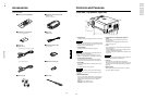
22
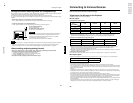
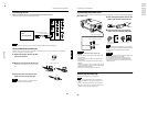
Connecting to Various Devices
Before connection, be sure to turn off the projector and connected devices.
Read the manual which comes with each device thoroughly.
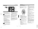
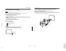
Signals that Can Be Input to the Projector
The following signals can be input to the projector:
■ Video signals
(1) Response to color systems
*1:Responds if Y/C output is available.
*2:Signifies that component signals (“Y, P
B
, P
R
” / “Y, B-Y, R-Y” / “G, B, R, H/C
S
, V”) conform to the signal timing
(synchronization and video period) of each color system. The color systems are used for convenience only.
(2)
Response to double density (*3), high-vision signals
*3:Signals whose density of scanning lines/field is twice as high.
*4:Responds to signals whose horizontal scanning frequency is 31.5 kHz. NTSC can be made twice as dense by a line
doubler (separately available: recommended article). Also, possible to respond to fully-specified, decoded
wide-clear-vision signal and decoded 525P progressive signal.
*5:Responds to signals whose horizontal scanning frequency is 33.5 kHz. PAL can be made twice as dense by a line doubler
(separately available: recommended article).
(3) Response to DTV-format signals
DTV-format signals (480i, 480p, 720p, 1080i) can be input to the Y, P
B
/B-Y, P
R
/R-Y, G, B, R, H/C
S
, V input terminal.
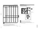
■ Computer signals
Signals with the following scanning frequencies can be input to the PC 1 or PC 2 (G, B, R, H/C
S
, V) and DVI terminals.
Be sure that the computer to be used suffices the following conditions:
• The computer has the video signal output port.
Be sure that the computer has the video signal output port by reading the instruction book of the computer.
The video signal output port is generally called as “RGB port”, “monitor port”, or “video port”. If the computer-monitor hybrid
type or note type is used, it may need to prepare for an external output port. Also, there will be the type to which an external
output port cannot be installed.
• DVI input
During DVI input, depending on the computer settings, there may be no signal input or an error may occur (blue screen).
If this happens, turn off the power to both the projector and the computer, and then turn the projector back on before turning
the computer on again. Then correctly set the computer's graphic board.
• The resolution and the scanning frequencies are within the range specified in the table on page 23.
Be sure that the resolution and the scanning frequencies of the video signal are within the range. A video signal out of range
cannot be used. (Even signals out of the range could be projected. However, it may not sharp enough. On the other hand,
even some of the signals within the range may require adjustment depending on the video board used.)
When a signal other than listed in the table on page 23 is input, the image could be partially erased or an unneeded fold-over
image could appear.
Even signals in the frequency range that can be input may not be displayed normally depending on the type of the signal.
Composite sync (C
S
) and G on Sync signals cannot be handled depending on the devices connected.
Color systems
Input terminal
NTSC NTSC4.43 PAL SECAM
VIDEO ‡‡‡‡
Y/C ‡
‡*
1
‡ - - - - -
Y, P
B
/B-Y, P
R
/R-Y ‡*
2
‡*
2
‡*
2
‡*
2
G, B, R, H/C
S
, V ‡*
2
‡*
2
‡*
2
‡*
2
Input terminal
NTSC*
4
NTSC*
5
High-vision signal
Y, P
B
/B-Y, P
R
/R-Y
‡‡‡
G, B, R, H/C
S
, V
‡‡‡
Horizontal scanning frequency 15kHz - 105kHz
Vertical scanning frequency 50Hz - 100Hz
21
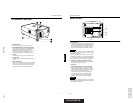
Installing the Projector
ENGLISHDEUTSHFRANÇAISITALIANOESPAÑOL
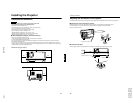
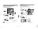
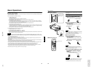
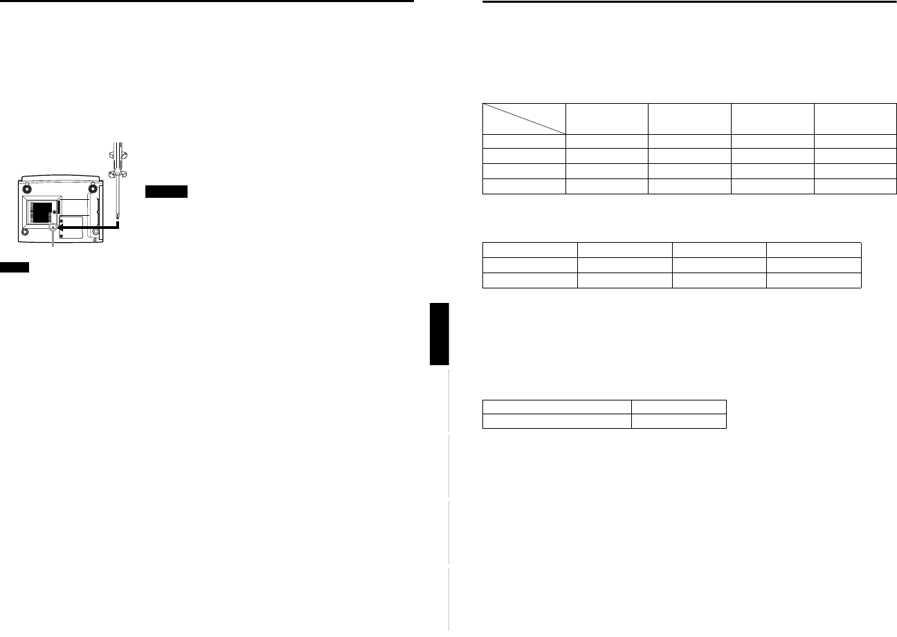
Setting the Position Selecting Screw for Ceiling Mounting
When using the projector in an upside-down, ceiling-mounted position (inverted top-to-bottom and right-to-left), the “position
selecting screw for ceiling mounting” must be turned to switch to ceiling mounting.
This will correct variance in color images (shading), which otherwise would occur in ceiling mounting.
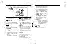
To revert to normal desktop setting, turn the “position selecting screw for ceiling mounting” back to the initial position (factory-
shipped).
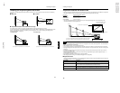
When using the projector in an upside-down, ceiling-mounted position:
Turn the “position selecting screw for ceiling mounting” fully counterclockwise (until it is turning idly).
To again use the projector in a normal desktop setting:
Turn the “position selecting screw for ceiling mounting” fully clockwise (until it firmly tightens).
For normal desktop mounting:
Turn the screw clockwise.
For upside-down, ceiling-mounting:
Turn the screw counterclockwise.
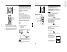
•To ceiling-mount and adjust the projector, special expertise and technique are
necessary. Be sure to ask your dealer or a specialist to perform this work.
•To turn the “position selecting screw for ceiling mounting”, use a Phillips
screwdriver with a 30-mm or longer shank.
The screw is located in the hole shown in the illustration.
Note
• When using the projector in a ceiling-mounted position, you should reverse the projected image by changing the settings of
Right Left rev. and Top Bottom inv. menus. For details, refer to page 54. You can also change these settings without
receiving a video signal. In this case, refer to “Menu Transition Diagram in No signal Menu Mode” on page 38.
When installing (adjusting/setting) the unit
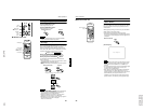
• When using “Top Bottom inv.” on the “Options” menu, reset the unit by following the procedure below.
• This reset procedure must be performed before operating the unit.
1. Change the “Top Bottom inv.” Setting on the “Options” menu.
2. Press the OPERATE button to enter the unit into the stand-by mode.
3. Press the OPERATE button again to turn on the unit.
• Adjust the focus after projecting a picture for 30 minutes or longer.
Position selecting screw for ceiling mounting
CAUTIONS