


7-4
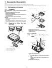
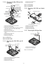
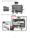
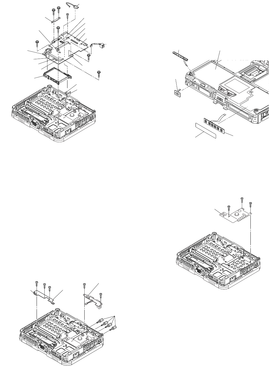
7.1.10. Removing the Main PCB and Lith-
ium Battery
1. Disconnect the Cable from Connector(CN3).
2. Remove the Lithium Battery.
3. Disconnect the seven Cables from seven Connectors
(CN9, CN12, CN14, CN23, CN30, CN35, CN36).
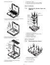
4. Remove the Screw <L>.
5. Remove the two Screws <M>.
6. Disconnect the two Cables from two Connectors (CN8,
CN17).
7. Remove the four Screws <N>.
8. Remove the Main PCB.
9. Remove the PCMCIA Unit.
Screw <L>:DRSB2+5FKL
Screws <M>:DXYN2+J12FNL
Screws <N>:DXYN2+J18FNL
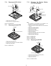
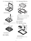
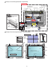
7.1.11. Removing the PAD PCB and I/O
PCB
1. Disconnect the Cable from Connector (CN801).
2. Remove the three Screws <O>.
3. Remove the PAD PCB.
4. Remove the four Screws <P>.
5. Remove the two Screws <Q>.
6. Remove the I/O PCB.
Screws <O>:DFHE5025XA
Screws <P>:DFHE5058ZB
Screws <Q>:DRSB2+5FKL
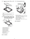
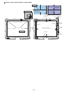
7.1.12. Removing LED PCB and Switch
PCB
1. Remove the LED Waterproof Sheet.
2. Remove the LED PCB.
3. Remove the Switch PCB.
4. Remove the Power Switch.
7.1.13. Removing the CPU Heat Plate
1. Remove the three Screws <R>.
2. Remove the CPU Heat Plate.
Screws <R>:DFHE5025XA
<L>
<M>
<M>
<N>
<N>
<N>
<N>
HDD Guid Plate
Connector (CN36)
Connector (CN35)
Connector (CN30)
PCMCIA Unit
to Connector (CN17)
Connector (CN3)
Connector (CN17)
Connector (CN8)
Connector (CN9)
Connector (CN14)
Connector (CN12)
LAN Cable
Main PCB
to Connector (CN8)
Connector
(CN23)
Lithium Battery
<O>
<O>
<O>
<Q>
<P>
<Q>
I/O PCB
PAD PCB
Connector
(CN801)
LED Waterproof Sheet
LED PCB
Power
Switch
Knob
Operation Sheet
Switch PCB
<R>
<R>
<R>
CPU Heat Plate