


7-6
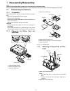
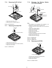
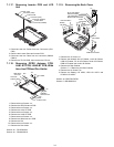
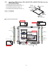
7.1.17. Removing Inverter PCB and LCD
Unit
1. Disconnect the two Cables from two Connectors (CN1,
CN2).
2. Remove the Inverter Case and Inverter PCB.
3. Disconnect the two Cable from two connector (CN900,
CN901).
4. Remove the TS PS2 PCB, then remove the LCD unit.
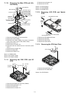
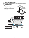
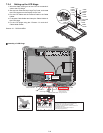
7.1.18. Removing GPRS Antenna PCB,
LAN1-BT PCB, LAN2-BT PCB, Wide
Area Aux PCBand Pen Holder
1. Remove the two Screws <a>.
2. Remove the GPRS Antenna PCB
3. Remove the two Screws <a>.
4. Remove the LAN1-BT PCB.
5. Remove the two Screws <a>.
6. Remove the LAN2-BT PCB.
7. Remove the two Screws <a>.
8. Remove the Wide Area Aux PCB.
9. Remove the Pen
10. Remove the two Screws <b>.
11. Remove the Pen Holder.
Screws <a> : DFHE5025XA
Screws <b> : DRHM5025YA
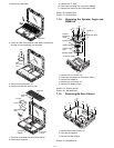
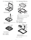
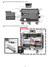
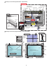
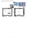
7.1.19. Removing the Each Cover
1. Remove the 12 Screws <f>.
2. Remove the Moden/LAN LID Rubber, LAN LID Rubber,
USB LID Rubber, DC IN LID Rubber, Serial LID Rubber,
RGB LID Rubber and Audio LID Rubber.
3. Remove the Rear Cabinet.
(Refer to 7.1.5 Removing the Rear Cabinet)
4. Remove the six Screws <e>.
5. Remove the Battery LID ASS'Y, HDD LID ASS'Y and
PCMCIA LID ASS'Y.
Screws <e>:DRQT26+D3FKL
Screws <f>:DRHM5025YA
Inverter Case
Connector (CN2)
Connector (CN1)
Inverter PCB
TS PS2 PCB
Connector (CN901)
Connector (CN900)
<b>
<a>
<a>
<a>
<a>
<b>
Pen Holder
LAN2-BT
Antenna PCB
GPRS
Antenna PCB
Pen
Wide Area
Aux PCB
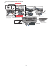
<a>
<a>
<a>
<a>
LAN1-BT
Antenna PCB
<f>
PCMCIA LID ASS’Y
DC IN LID Rubber
USB LID Rubber
LAN LID Rubber
Moden/LAN LID Rubber
Audio
LID Rubber
HDD LID ASS’Y
Battery
LID ASS’Y
<f>
<e>
<e>
<e>
<e>
<f>
<e>
<f>
RGB
LID Rubber
Serial
LID Rubber
<f>
<f>
<f>