


7-24
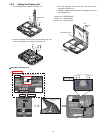
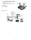
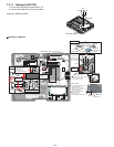
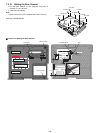
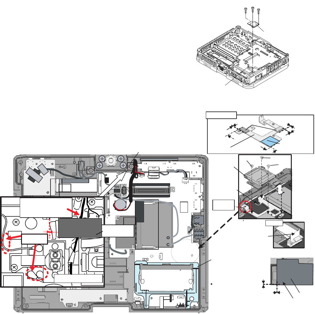
7.2.11. Setting the SD PCB
1. Fix the SD PCB using the three Screws <h>.
2. Connect the Cable to the Connector (CN21).
Screws<h>:DXQN2+A22FNL
! Assembly of SD PCB
<h>
<h>
<h>
SD PCB
Connector (CN21)
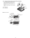
Note for cable
arrangement
Only for the Antenna Cable
Insert the surplus length
under the Board.
Do not insert the Coin
Battery Cable underthe Board.
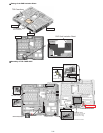
Sub material:
PET TAPE 2
(10 mm width x 3 cm)
0~3mm
Not necessary for model
without the Antenna Cable
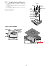
Avoid running
over the Cable.
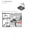
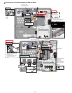
Screw
Screw
Screw
SD Sheet
Screw
SD Angle
Cable Holder Sheet
DIMM Holder
Insert it into the boss
as it comes over the Cable.
0~0.5mm
0~0.5mm
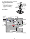
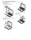
SD ANGLE Assy
SD ANGLE
ASSY
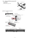
SD PCB
FFC
Do not bend on the stiffening plate.
(Bend it at 1 mm away
from the stiffening plate.)
Avoid running
over the positioning
pin of the SD Angle.
0~0.5mm
0~0.5mm
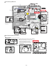
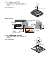
Two-sided tape
0~0.5mm
0~0.5mm
0~0.5mm
0~0.5mm
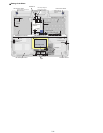
Set the SD Board and then connect
to the DIMM Connector.
*Before connecting, confirm
the Spacer is not attached
on the Main Board.
Only for model with DIMM
Release the Hooks
on the both sides
before setting the DIMM Holder.
SD Angle
Spacer 2
SD Angle Spacer 1