


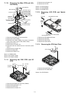
7-8
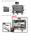
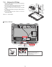
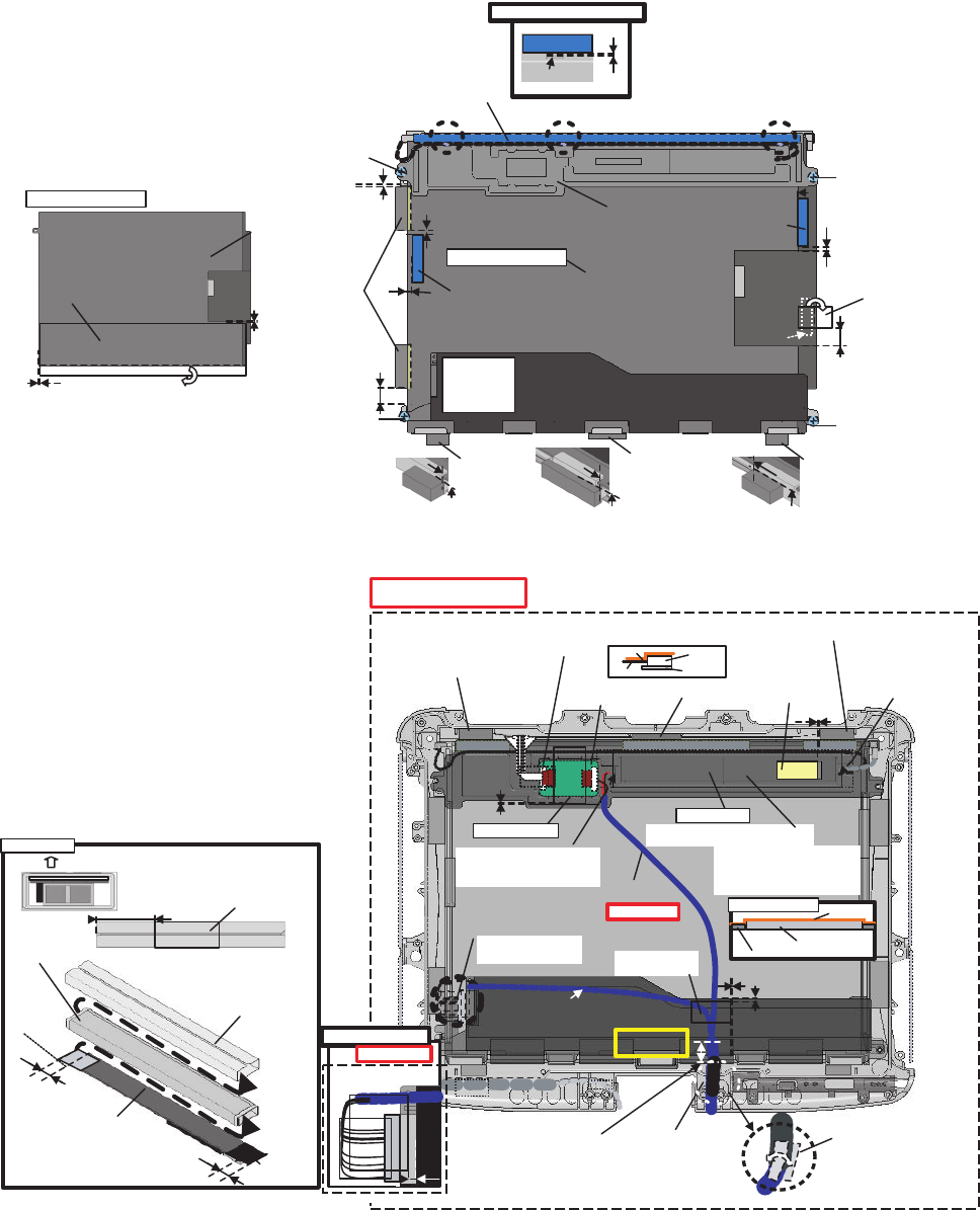
! Assembly of LCD Back Damper (Applicable Model : Digitizer Model)
! Assembly of Inverter PCB (Applicable Model : Touch Screen Model)
Fold back the surplus length.
0~0.5mm
0~0.5mm
Digitizer PCB Assy
Pass the Cable
under the protrusion.
Detail of "A/B/C"
0~0.5mm
2±0.5mm
4±0.5mm
2±0.5mm
A
0~3mm
BC
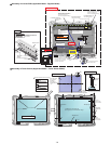
Remove the Release Paper on the back side and attach it.
Lengthwise: Match to the LCD Frame.
Crosswise: Match to the middle line.
10±2mm
0±0.5mm
10±2mm
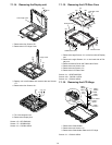
Screw the Board together.
Screw the
Digitizer and
the LCD Back
Dumper together.
Screw the Digitizer
and the LCD Back Dumper together.
Screw the Board together.
Ensure the
Connector is
connected
securely.
Fold back the half length,
and attach to the LCD side.
Digitizer PCB Assy
Attach it to the side
surface of the Frame.
(Match to the end of
the Frame within 0 to 0.5 mm
at the far side.)
Handle it carefully.
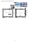
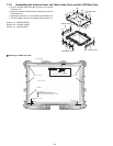
Screw
Digitizer
LCD Back Cushion DG CCFL
Screw
Tape
Screw
LCD Side Cushion CLCD Side Cushion D
LCD Side
Cushion C
LCD Back Cushion DG Side
LCD Back
Cushion
DG Side
LCD Back Dumper
LCD Side
Cushion A
Screw
Digitizer Sheet
0±0.5mm
0±0.5mm
0±0.5mm
0±0.5mm
0±0.5mm
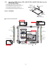
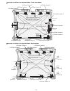
Conductive Tape
ANT Cable Cushion
Caution High
Voltage Label
Insulation Parts
INV MIL Sheet
Inverter Case MIL
LCD Side Cushion E
LCD Side Cushion E
LCD Side Cushion F
TS PWB
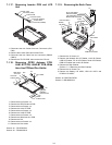
Insert
Insert
5~6mm
5~6mm
pasted on the connector
after it is wound around
the cable twice.
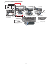
Inverter Assy
( "Gap side" is front.)
LCD REAR Side
Inverter Assy
0~3mm
Don’t give stress to LCD TAB.
0~0.5mm
A
Wrap.
Connect the Cable to the left
and right Connectors.
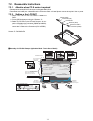
0~3mm
Attach so the Inverter Assy
comes at the center,
and attach the left and right
surplus length to the Back Dumper
as illustrated below.
Insert between the ribs.
Insert
Prevent FPC from coming off.
Connector
PWB
FPC
12
Detail of "A"
1~2
mm
Confirm a "Insulation
Parts" isn’t frayed.
Pay attention to the direction of
the INVERTER PCB when doing
this installation.
Safety Working
PET TAPE 1
30~35mm
Insert between the ribs.
Insert between
the ribs.
Avoid any stress on the Cable
when connecting it to the Inverter.
(Hold the Connector part
when connecting/disconnecting.)
Avoid any stress on the Cable
when connecting it
to the Inverter.
(Hold the Connector part
when connecting
/disconnecting.)
Inverter Assy
LCD Back Dumper
Carefully attach Tape
Tape
CCFL
Connector
side
LCD Cable Connector side
Wrap over the Antenna Cable
Cushion and the Cable.
6–2mm from
the branch point
Fix the two Cables.
Avoid getting under the Sheet.
INV Sheet 1
(Black)
Inverter
INV Sheet 2
(Translucence)
INV MIL Cover
Tape
LCD Cable
Sield Sheet
Insulation Parts
Safety Working
Safety Working