


7-20
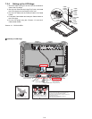
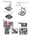
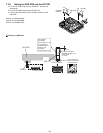
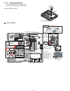
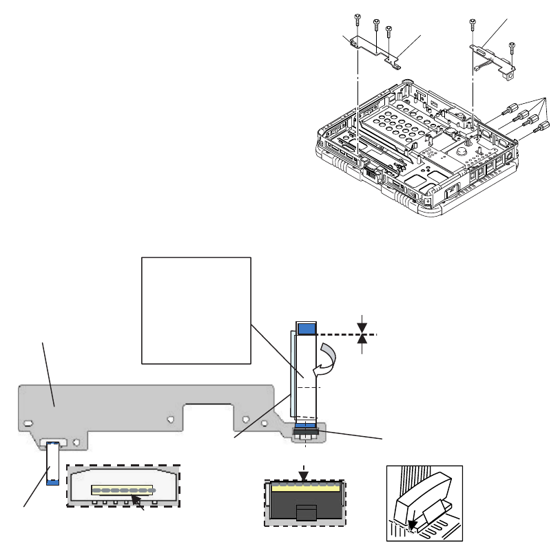
7.2.9. Setting the PAD PCB and the I/O PCB
1. Fix the I/O PCB using the four Screws<P> and the two
Screws<Q>.
2. Fix the PAD PCB using the three Screws<O>.
3. Connect the SW Cable to the Connector (CN801) of the
PAD PCB.
Screws <O>:DFHE5025XA
Screws <P>:DFHE5058ZB
Screws <Q>:DRSB2+5FKL
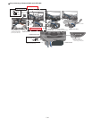
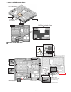
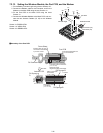
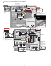
! Assembly of PAD PCB
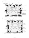
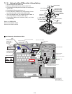
<O>
<O>
<O>
<Q>
<P>
<Q>
I/O PCB
PAD PCB
Connector
(CN801)
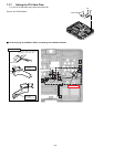
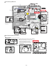
FFC CN Stopper
PAD PCB
SW FFC
Connector surface
Connector surface
Match to the center
of the Connector.
Fold back and attach.
Allowable misalignment
of the edges
0~1.5mm
0~1mm
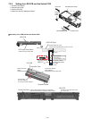
Sub material:
PET TAPE 1
(19 mm width x 3 cm)
For models with
measures against
whiskers, use
the Tape of
19 mm width x 2 cm
PAD FFC