


7-27
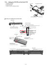
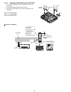
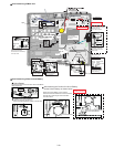
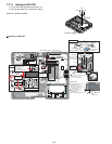
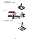
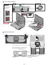
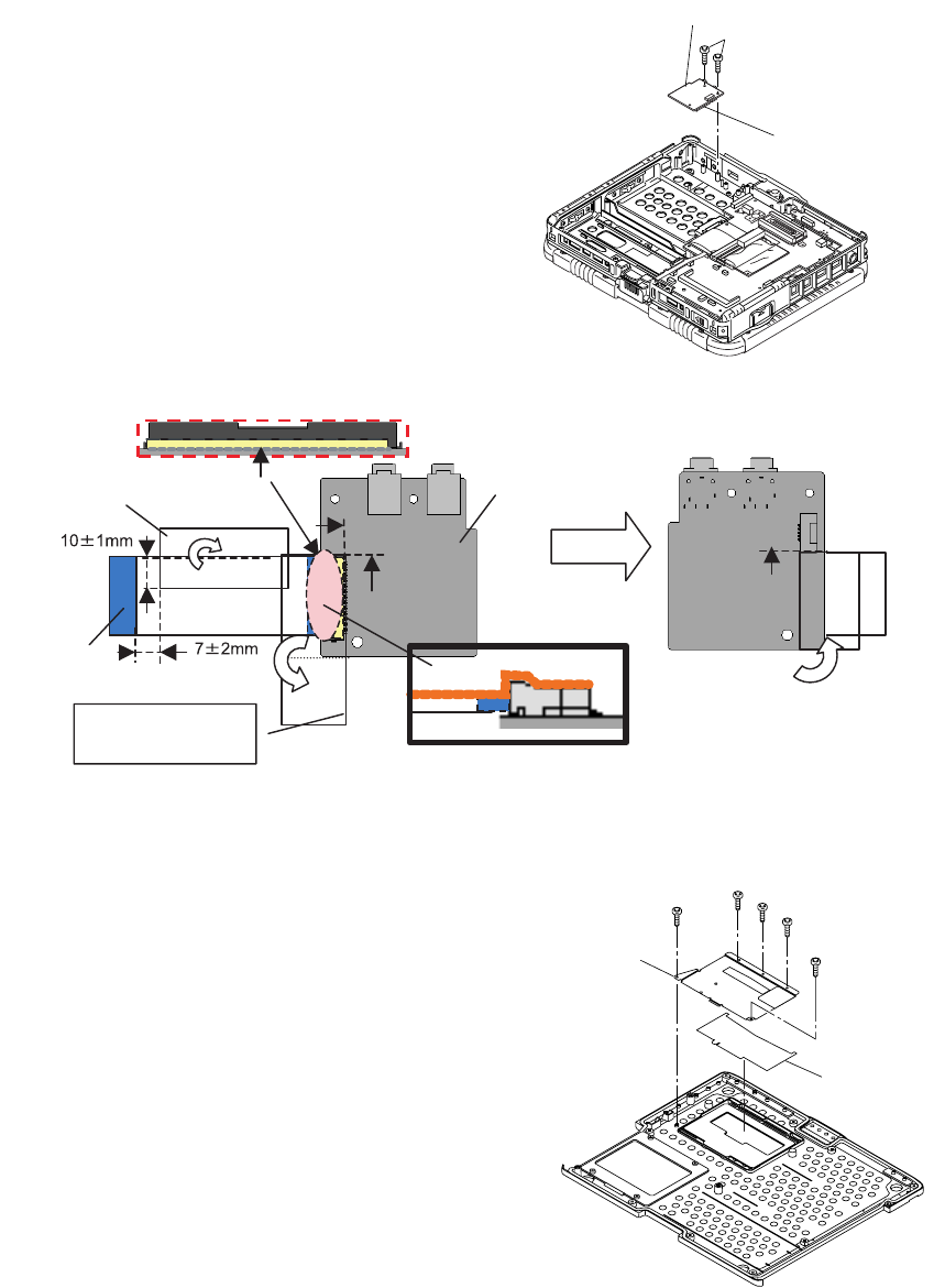
7.2.13. Setting the Audio PCB
1. Connect the Cable to the Connector of the Audio PCB
(CN901), and fix the Audio PCB using the two
Screws<H>.
Screws<H>:DRSB2+5FKL
! Putting of the Sheet
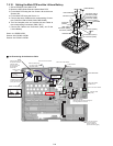
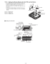
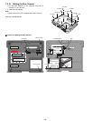
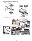
7.2.14. Assembling the DU Lid Unit
1. Fix the DU Lid Angle and the DU Lid using the five
Screws<G>.
Screws <G>:DRHM5025YA
Connector (CN901)
Audio PCB
<H>
Audio PCB
Audio FFC
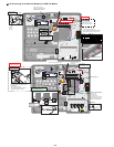
Sheet(for EMI)
Connector surface
Confirm the direction of the FFC when connecting.
Sub material:
PET TAPE 1
(19 mm width x 5.5 cm)
Attach it along the
surface of the Connector
and the FPC.
Ensure it does
not run over
the Connector
by 0.1 mm or more.
Back side
<G>
<G>
<G>
<G>
<G>
DU LID
DU LID Angle