


7-26
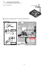
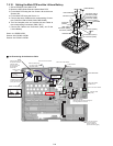
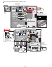
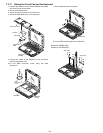
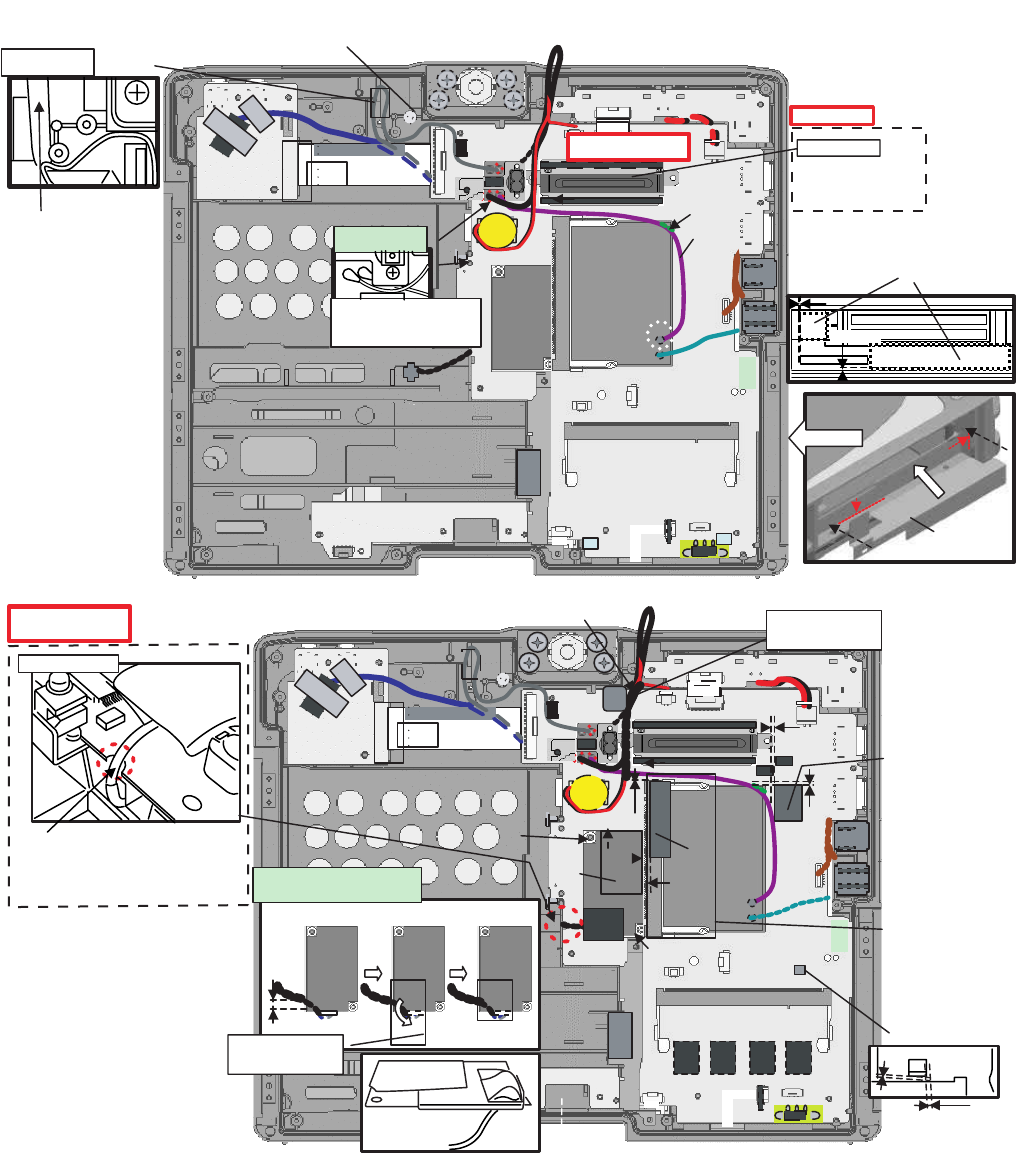
! Line Processing of the Wireless Module,Port PCB and Modem
Gasket
Mini PCI Card Sheet
DU Sponge A
0~1mm
0~1mm
0~0.5mm
Ensure it is set
in the Hooks
on the both sides
of the receiving Connector.
0~0.5mm
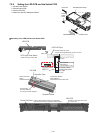
Pass it at the right of the Coil.
Wind the coil
securely to avoid
coming off.
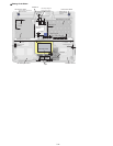
Attach the insulation sheet
for the Modem Cable.
Remove the Modem PCB before using
the Tape and the Screw.
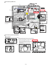
Sub material:
PET TAPE 1
(19 mm width x 4 cm)
Sub material:
PET TAPE 1
(19 mm width x 4 cm)
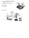
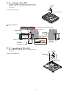
5–2mm
(Not necessary for model
without W-LAN Module)
Pass the Cables through the notch
of the Board.
*Do not bend sharply.
Avoid rubbing against the Board
and damaging of the Cable.
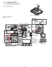
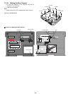
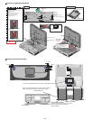
Safety Working
Screw
Screw
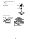
Tape
DU Sponge C
Modem Cable
Fold back and attach.
1~2mm
1~2mm
0~0.5mm
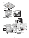
..
Tape
Cable Holder Sheet
DU PCB ASSY
Insert it into the boss
as it comes over the Cable.
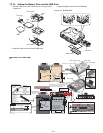
Safety Working
Pass the Cable
under the card.
1
Pass it under the Coin
Battery Cable and fix it.
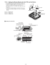
Details of cable
arrangement
Side surface
Insert the end of the Sheet
into the space between the Main Board
and the bottom of the LAN Connector.
Cable
PCMCIA Sheet
Details of cable
arrangement
Pass the Black Cable over
the Gray Cable and connect
them. Draw them sideways
in parallel as shown above.
Tape up
to the
far side.
0~0.5mm
0~0.5mm
Safety Working