


7-25
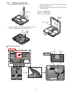
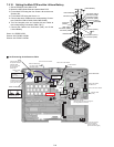
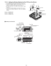
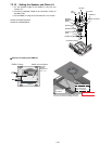
7.2.12. Setting the Wireless Module, the Port PCB, and the Modem
1. Fix the Battery Connect Angle using the two Screws <K>.
2. Connect the Modem cable to the Connector, and fix the
Modem on the Main PCB using the two Screws <J>.
3. Fix the Port PCB on the Main PCB using the three
Screws <I>.
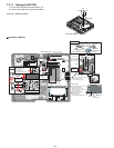
4. Connect the Wireless Module to the Main PCB, and con-
nect the two Antenna Cables (J5, J6) to the Wireless
Module.
Screws <I>:DRSB2+5FKL
Screws <J>:XSB2+4FNL
Screws <K>:DRSB2+5FKL
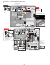
! Assembly of the Port PCB
<K>
<J>
<K>
<I>
<I>
Bat Con Angle
Connector (J5)
Connector (J6)
Modem
Port PCB
Wireless Module
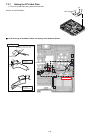
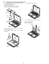
<I>
<J>
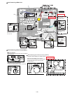
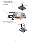
DU Connetor Angle
Tape
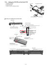
DU Sponge B
DU Sponge
D
Antenna PCB
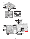
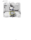
0~0.5mm
Back side
Match to the center
of the Board.
(-1 to +1 mm)
0~0.5mm
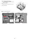
Ensure the Board does not
run over the dowel.
Ensure it does not come
over the end of the Board
by 0.5 mm or more.
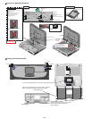
Match the center of the Sheet
to the end of the DU Connector.
(-1 to +1 mm)
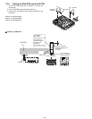
Attach the surplus
length to the edge of the Board.
Port PCB
Portre Sheet
0~0.5mm
DU Sponge B
0~0.5mm
0~0.5mm
Match to the center
of the Board.
(-1 to +1 mm)