


7-19
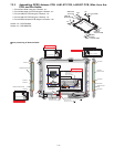
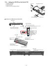
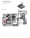
7.2.8. Setting the LED PCB and the Switch PCB
1. Set the Power Switch.
2. Set the Switch PCB.
3. Set the LED PCB.
4. Attach the new LED Waterproof Sheet.
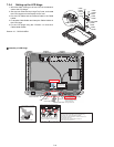
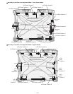
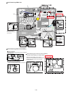
! Assembly of the LED PCB and the Switch PCB
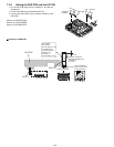
LED Waterproof Sheet
LED PCB
Power
Switch
Knob
Operation Sheet
Switch PCB
LED Light Guide Sheet
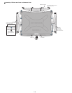
Operation Tape
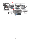
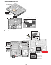
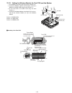
LED PCB
SW PCB
Operation Sheet
LED PCB Tape
LED FFC
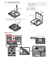
Match the frame
edges
and attach them.
Connector surface
Avoid coming
off of the LED part,
or running over the LED part.
Avoid running over the LED.
Ensure it does not come
over the end of the Board by 0.5 mm or more.
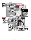
Sub material:
PET TAPE 1
(19 mm width x 3 cm)
0~3mm
Fold back and attach.
Allowable misalignment
of the edges
0~1.5mm
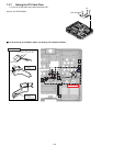
Back side
Confirm the direction
when attaching.
CN bracket is on the back side.
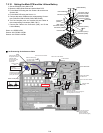
0~5mm
Power SW Knob
Perform the operation check for a few times,
and ensure the smooth operation without noise.
SW PCB
Match to the upper left corner.
0 to 0.5 mm