


7-22
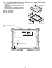
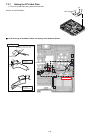
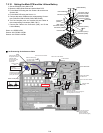
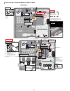
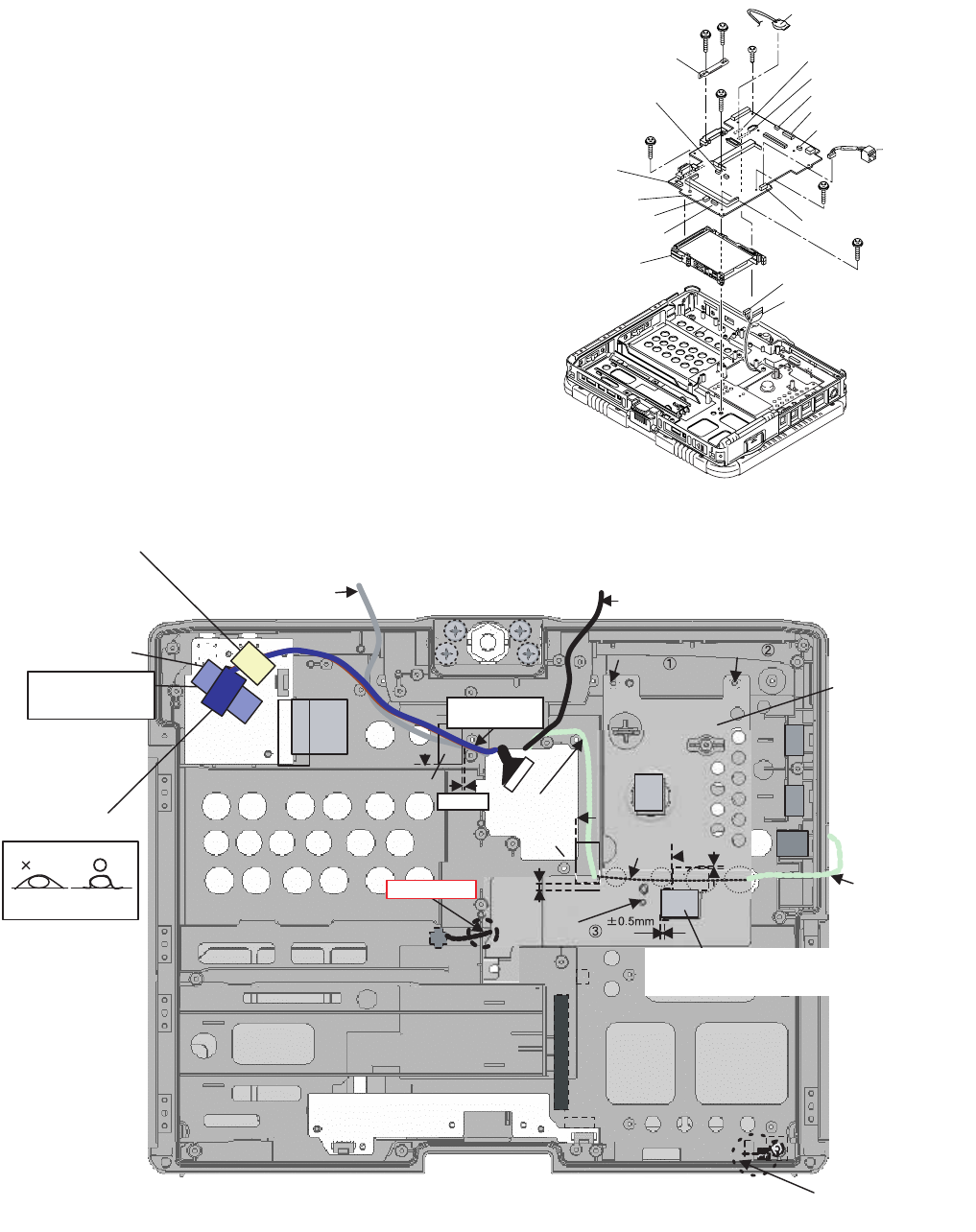
7.2.10. Setting the Main PCB and the Lithium Battery
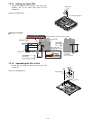
1. Set the PCMCIA Unit to Main PCB
2. Mount the HDD Guide Plate and set the Main PCB.
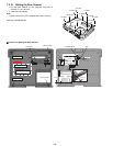
3. Fix the Main PCB using the four Screws <N> and the two
Screws <M>.
4. Fix the Main PCB using the Screw <L>.
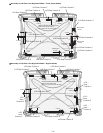
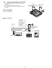
5. Connect the seven Cables to the corresponding Connec-
tors (CN9,CN12,CN14,CN23,CN30,CN35,CN36).
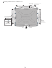
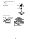
6. Turn the computer over and connect the two Cables to
the corresponding Connectors (CN8, CN17).
7. Connect the Cable to the Connector (CN3), and fix the
Lithium Battery.
Screw <L>:DRSB2+5FKL
Screws <M>:DXYN2+J12FNL
Screws <N>:DXYN2+J18FNL
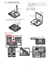
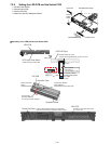
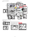
! Line Processing of the Antenna Cable
<L>
<M>
<M>
<N>
<N>
<N>
<N>
HDD Guid Plate
Connector (CN36)
Connector (CN35)
Connector (CN30)
PCMCIA Unit
to Connector (CN17)
Connector (CN3)
Connector (CN17)
Connector (CN8)
Connector (CN9)
Connector (CN14)
Connector (CN12)
LAN Cable
Main PCB
to Connector (CN8)
Connector
(CN23)
Lithium Battery
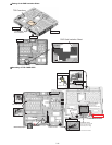
Details for attachment
Tape
Cable Holder(Cap)
CPU Heat Plate
Antenna Cable (Gray)
If no Gray Cable, use
the Brown Cable.
Antenna Cable
(black)
Antenna Cable
(white)
(0 to 0.5 mm from the
end of the cabinet)
Check a position of
power swich knob.(right)
Antenna Cable
(blue)
Attach as shown above
to avoid coming off.
Arrange the Cables,
and then set it.
Avoid running over
the Connector
and the bis.
Avoid running
over the boss.
Pass it beside
the pin.
0~1mm
1~2mm
Draw it out of the cabinet.
Draw it out of the cabinet.
Draw it out of the cabinet.
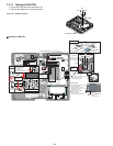
Sub material:
PET TAPE 1
(19 mm width x 3 cm)
Draw it out of the cabinet.
Safety Working
Sub material is not
necessary if the Tape
and the Cable Holder
(CAP) are not used.
Use the Tape only for
the position with the
Antenna Cable.
)
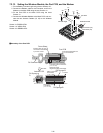
Screw
Screw
Screw
Heat Dissipation
Rubber
Tape
Tape
0~1mm
0~2mm
Pass it between
the bosses.
0~2mm
Match the left end to the marking line.
Fit it lengthwise in the frame.
Heat Dissipation Rubber