


7-11
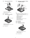
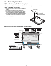
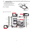
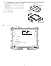
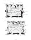
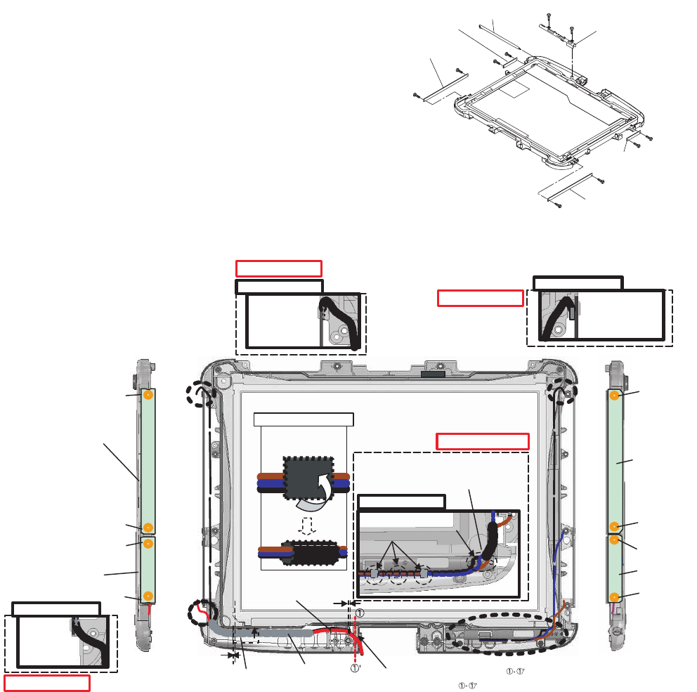
7.2.3. Assembling GPRS Antenna PCB, LAN1-BT PCB, LAN2-BT PCB, Wide Area Aux
PCB, and Pen Holder
1. Fix the Pen Holder using the 2 Screws. <b>
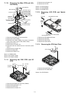
2. Fix the Wide Area Aux PCB using the 2 Screws. <a>
3. Fix the LAN2-BT PCB using the 2 Screws. <a>
4. Fix the LAN1-BT PCB using the 2 Screws. <a>
5. Fix the GPRS Antenna PCB using the 2 Screws. <a>
Screws <a> : DFHE5025XA
Screws <b> : DRHM5025YA
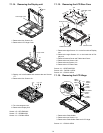
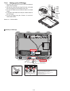
! Line processing of Antenna Cable
<b>
<a>
<a>
<a>
<a>
<b>
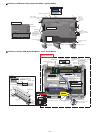
Pen Holder
LAN2-BT
Antenna PCB
GPRS
Antenna PCB
Pen
Wide Area
Aux PCB
<a>
<a>
<a>
<a>
LAN1-BT
Antenna PCB
Screw<a>
Screw<a>
Screw<a>
Screw<a>
Screw<a>
Wide Area Aux
PCB
LAN1-BT
Antenna PCB
Screw<a>
Screw<a>
Screw<a>
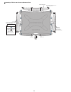
GPRS Antenna PCB
Tape
Sheet(For EMI)
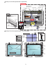
Ensure the white Cable is coming out
by 31 cm or more from the right edge ( )
of the Front Case.
More than 31cm from
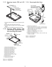
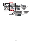
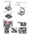
Detail of "A"
A
B
C
Detail of "B"
Detail of "C"
Be free of overhang..
Insert this between two ribs after pasting
Cable Cushion.
Be free of overhang..
Be free of overhang..
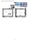
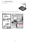
Detail of "D"
D
Bundle and wind 2 cables.
0–3mm
0~1mm
Bundle and wind 3 cables.
Hook it.
Insert cables between four pins.
Safety Working
Be free of overhang..
Attach it to the inner
side of the right rib.
LAN2-BT Antenna PCB
Cable Cushion
Cable Cushion
Cable Cushion
B
Safety Working
Safety Working
Safety Working