


141
CHAPTER 3 SPECIFICATIONS
3
3.4 Buffer Memory Assignment
3.4.2 Details of the buffer memory
When CT ratio setting is used (0.0 to 100.0A) (2) is selected, the setting of CT CT ratio setting (Un\G288 to Un\G295) is
enabled. In advance, set CT CT ratio setting (Un\G288 to Un\G295) corresponding to the sensor to be connected. After
that, select When CT ratio setting is used (0.0 to 100.0A) (2).
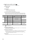
(56)CT Reference heater current value (Un\G280 to Un\G287)
Set the reference value of CT Heater current process value (Un\G256 to Un\G263) of when the heater is turned
on ( Page 138, Section 3.4.2 (53)).
(a) Supported modules
• Q64TCTTBWN
•Q64TCRTBWN
(b) Setting range
The setting range is within the heater current range of the current sensor selected in CT CT selection
(Un\G272 to Un\G279). ( Page 140, Section 3.4.2 (55))
(c) Default value
The default values are set to 0 (0.0A) for all terminals.
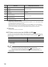
(57)CT CT ratio setting (Un\G288 to Un\G295)
Set the number of second-winding (turning number) of the current sensor (CT) to be connected.
This buffer memory area is available only when CT CT selection (Un\G272 to Un\G279) is set to When CT ratio
setting is used (0.0 to 100.0A) (2). ( Page 140, Section 3.4.2 (55))
(a) Supported modules
• Q64TCTTBWN
•Q64TCRTBWN
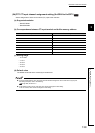
(b) Setting range
The setting range is 600 to 9999.
(c) Default value
The default values are set to 800 for all terminals.
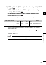
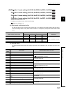
Setting of CT CT selection (Un\G272 to Un\G279) Setting range
• When CTL-12-S36-8 is used (0.0 to 100.0A) (0)
• When CT ratio setting is used (0.0 to 100.0A) (2)
0 to 1000 (0.0 to 100.0A)
When CTL-6-P(-H) is used (0.00 to 20.00A) (1) 0 to 2000 (0.00 to 20.00A)
Common
Common