


38
CHAPTER 3 SPECIFICATIONS
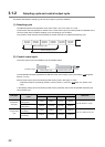
This chapter describes the performance specifications of the Q64TCN, I/O signals transferred to/from the CPU
module, and the specifications of the buffer memory.
For the general specifications of the Q64TCN, refer to the following.
QCPU User's Manual (Hardware Design, Maintenance and Inspection)
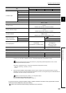
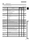
3.1 Performance Specifications
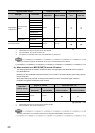
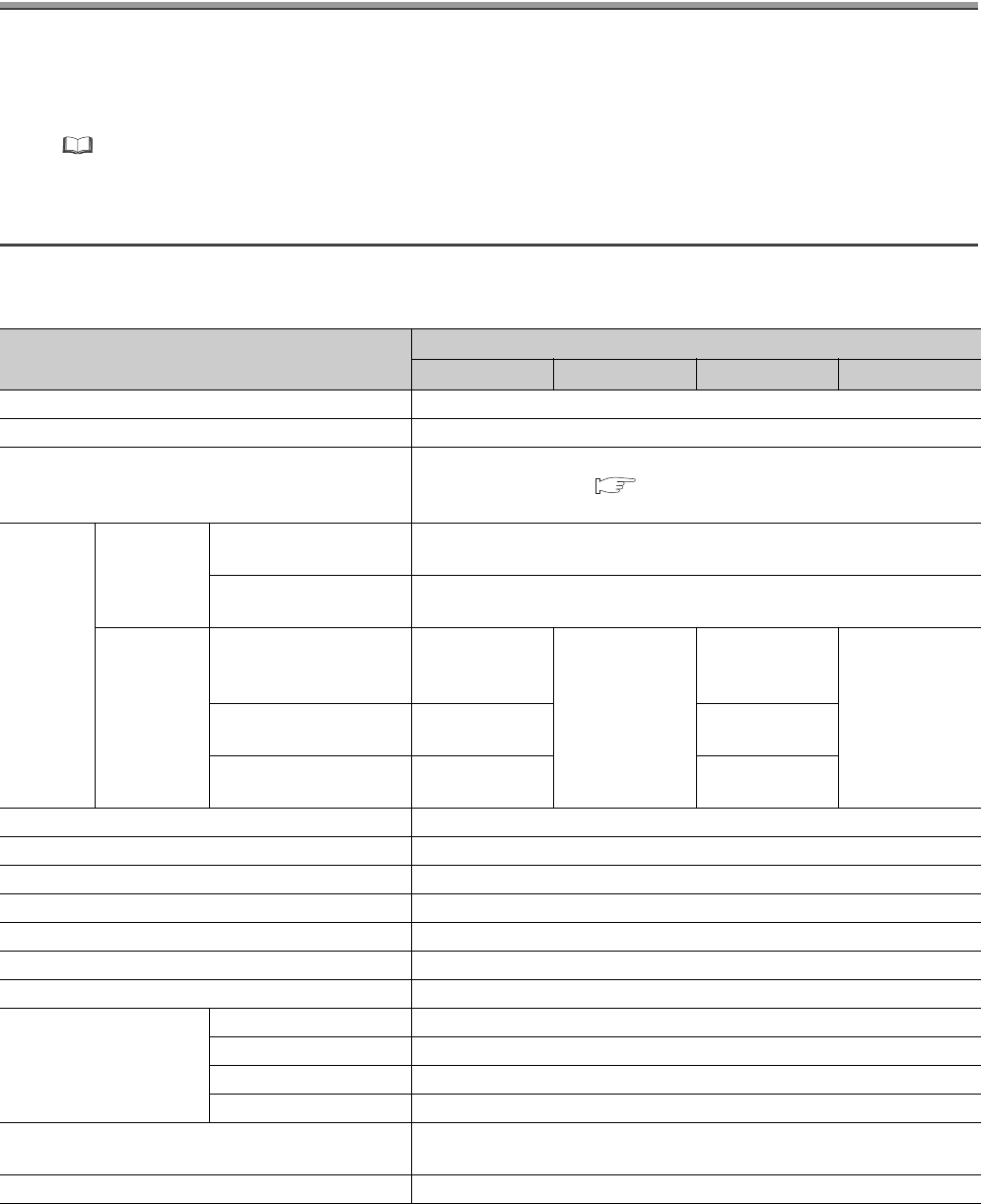
The following table lists the performance specifications of the Q64TCN.
Item
Specifications
Q64TCTTN Q64TCRTN Q64TCTTBWN Q64TCRTBWN
Control output Transistor output
Number of temperature input points 4 channels/module
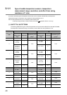
Type of usable temperature sensors, the temperature
measurement range, the resolution, and the effect from
wiring resistance of 1
Page 40, Section 3.1.1
Accuracy
*1
Indication
accuracy
Ambient temperature:
25±5°C
Full scale × (±0.3%)
Ambient temperature: 0 to
55°C
Full scale × (±0.7%)
Cold junction
temperature
compensation
accuracy:
(ambient
temperature:
0 to 55°C)
Temperature process
value (PV): -100°C or
more
Within ±1.0°C
Within ±1.0°C
Temperature process
value (PV): -150 to -100°C
Within ±2.0°C Within ±2.0°C
Temperature process
value (PV): -200 to -150°C
Within ±3.0°C Within ±3.0°C
Sampling cycle 500ms/4 channels (constant independently of the number of channels used)
Control output cycle 1 to 100s
Input impedance 1M
Input filter 0 to 100s (0: Input filter OFF)
Sensor correction value setting -50.00 to 50.00%
Operation at sensor input disconnection Upscale processing
Temperature control method PID ON/OFF pulse or two-position control
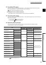
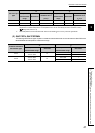
PID constants range
PID constants setting Can be set by auto tuning.
Proportional band (P) 0.0 to 1000.0% (0: Two-position control)
Integral time (I) 0 to 3600s (set 0 for P control and PD control.)
Derivative time (D) 0 to 3600s (set 0 for P control and PI control.)
Set value (SV) setting range
Within the temperature range set in the used thermocouple/platinum resistance
thermometer to be used
Dead band setting range 0.1 to 10.0%