


281
CHAPTER 5 SETTINGS AND THE PROCEDURE BEFORE OPERATION
5
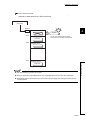
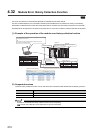
5.3 Part Names
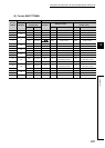
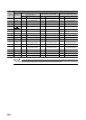
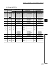
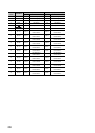
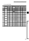
(2) For the Q64TCTTBWN
Terminal
number
Terminal block for CT Terminal block for I/O
Indication
Common to the all
control modes
Indication
Standard control
Heating-cooling control
(normal mode)
Symbol Name Symbol Name Symbol Name
1 NC NC Unused OUT1 L1 CH1 Output L1H CH1 Heating output
2
CT1
CT1 CT input 1 OUT2 L2 CH2 Output L1C CH1 Cooling output
3 CT1 CT input 1 OUT3 L3 CH3 Output L2H CH2 Heating output
4
CT2
CT2 CT input 2 OUT4 L4 CH4 Output L2C CH2 Cooling output
5 CT2 CT input 2 COM- Output common COM- Output common
6
CT3
CT3 CT input 3 NC NC Unused NC Unused
7 CT3 CT input 3 IN1 1+ CH1+ CH1 Thermocouple + CH1+ CH1 Thermocouple +
8
CT4
CT4 CT input 4 IN2 2+ CH2+ CH2 Thermocouple + CH2+ CH2 Thermocouple +
9 CT4 CT input 4 IN1 1- CH1- CH1 Thermocouple - CH1- CH1 Thermocouple -
10
CT5
CT5 CT input 5 IN2 2- CH2- CH2 Thermocouple - CH2- CH2 Thermocouple -
11 CT5 CT input 5 NC NC Unused NC Unused
12
CT6
CT6 CT input 6 CJ CJ
Cold junction temperature
compensation resistor
CJ
Cold junction temperature
compensation resistor
13 CT6 CT input 6 NC NC Unused NC Unused
14
CT7
CT7 CT input 7 CJ CJ
Cold junction temperature
compensation resistor
CJ
Cold junction temperature
compensation resistor
15 CT7 CT input 7 IN3 3+ CH3+ CH3 Thermocouple + MT3+ Monitor 3 thermocouple +
16
CT8
CT8 CT input 8 IN4 4+ CH4+ CH4 Thermocouple + MT4+ Monitor 4 thermocouple +
17 CT8 CT input 8 IN3 3- CH3- CH3 Thermocouple - MT3- Monitor 3 thermocouple -
18 NC NC Unused IN4 4- CH4- CH4 Thermocouple - MT4- Monitor 4 thermocouple -