


237
CHAPTER 4 FUNCTIONS
4
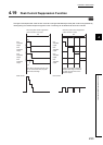
4.19 Peak Current Suppression Function
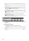
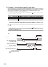
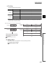
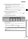
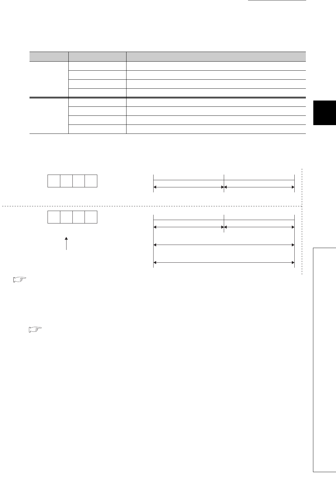
(c) Two timing
The following table shows two examples.
The following shows the relationship between groups and the values (%) of CH Upper limit output limiter
(Un\G42, Un\G74, Un\G106, Un\G138).
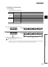
(3) Setting method
Set the timing in Peak current suppression control group setting (Un\G784).
For the setting, refer to the following.
Page 158, Section 3.4.2 (86)
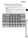
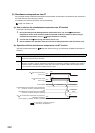
Example Channel Group
Example 1
CH1 Group 1
CH2 Group 1
CH3 Group 2
CH4 Group 2
Example 2
CH1 Group 1
CH2 Group 2
CH3 Not divided
CH4 Not divided
Peak current suppression control group setting (Un\G784)
Example 1
2211
0010 0010 0001 0001
Group 1 Group 2
50% 50%
CH1, CH2
Divided into
2 groups
CH3, CH4
Group 1 Group 2
50% 50%
CH1 CH2
Divided into
2 groups
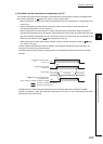
100% (In case of default value applied)
CH3
100% (In case of default value applied)
CH4
CH4 CH3 CH2 CH1
H
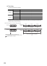
Example 2
0021
0000 0000 0010 0001
CH4 CH3 CH2 CH1
H
Whether the transistor output is executed or
not can be selected by CH3 Unused channel
setting (Un\G125) or CH4 Unused channel
setting (Un\G157).
Page 126, Section 3.4.2 (35)