


50
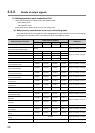
3.3.2 Details of input signals
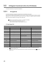
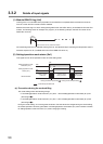
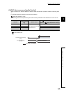
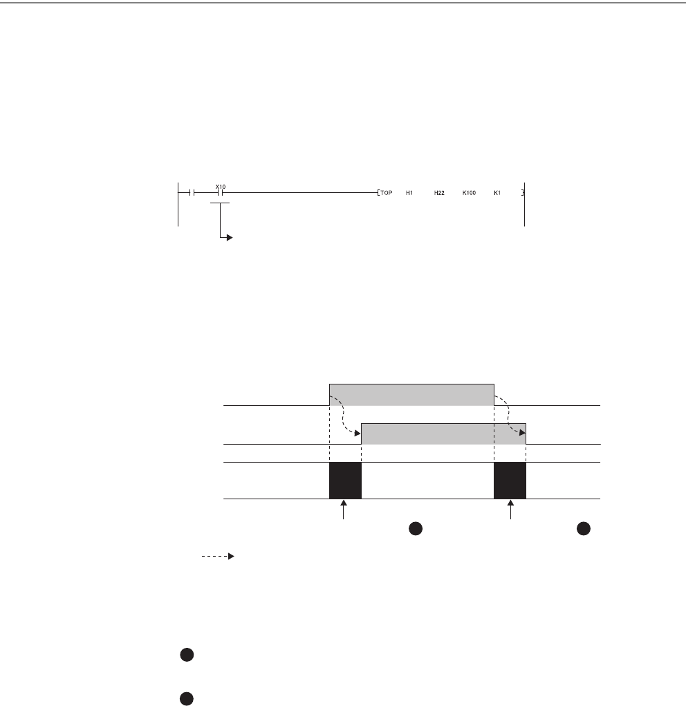
(1) Module READY flag (Xn0)
This flag turns on to indicate that the preparation for the Q64TCN is completed when the module is turned on
from off or when the CPU module's reset is released.
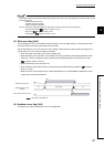
Make sure that this flag is on when reading/writing data from/in the buffer memory of the Q64TCN from the CPU
module. The following shows an example of a program. (In the following example, the start I/O number of the
Q64TCN is set to 10.)
If the watchdog timer error is detected, this flag turns off. The Q64TCN stops controlling the temperature and the
transistor output turns off. (The RUN LED turns off and ERR. LED turns on.)
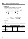
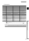
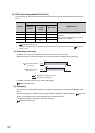
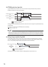
(2) Setting/operation mode status (Xn1)
This signal turns on at the operation mode, off at the setting mode.
(a) Precautions during the mode shifting
The mode shifting means the following timings.
• From Setting/operation mode instruction (Yn1) OFF ON to Setting/operation mode status (Xn1) ON
(above figure )
• From Setting/operation mode instruction (Yn1) ON OFF to Setting/operation mode status (Xn1) OFF
(above figure )
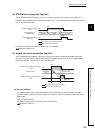
During the mode shifting, do not change the set values. If the set values are changed during the mode shifting,
the module operation cannot be guaranteed. Use Setting/operation mode status (Xn1) as an interlock condition
for Setting/operation mode instruction (Yn1) when changing the setting.
Write
instruction
Used as buffer memory read/write interlock.
Setting/operation mode
instruction (Yn1)
Setting/operation mode
status (Xn1)
Mode transition
Setting mode at
power-ON
ON
OFF
OFF
ON
During mode shift processing During mode shift processing
Setting mode
(after operation)
Operation mode
(during operation)
Executed by the Q64TCN
1 2
1
2