


307
CHAPTER 7 PROGRAMMING
7
7.2 When Using the Module in a Standard System Configuration
7.2.1 Standard control (such as auto tuning, self-tuning, and error code read)
7.2 When Using the Module in a Standard System
Configuration
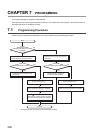
This section describes the following program examples.
7.2.1 Standard control (such as auto tuning, self-tuning, and error
code read)
This section describes the program example for operations such as the auto tuning, self-tuning, and error code read.
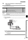
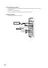
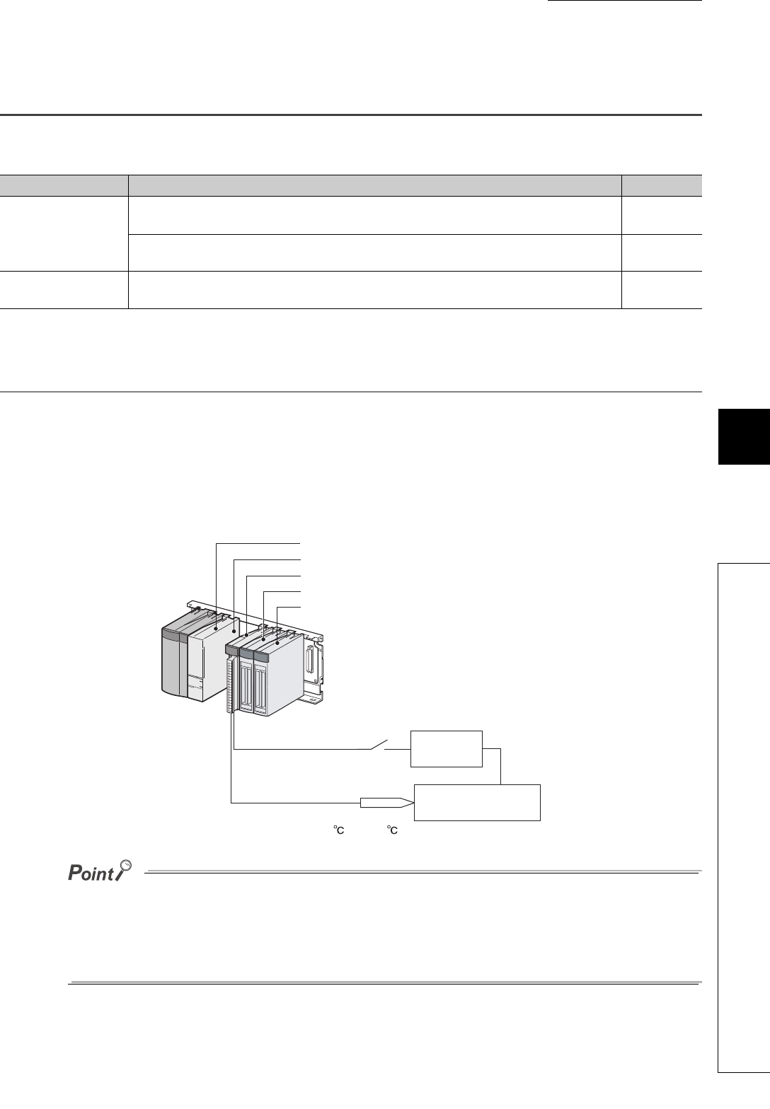
(1) System configuration
The following figure shows the system configuration for operations such as the auto tuning, self-tuning, and error
code read.
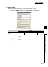
When the Q64TCTTBWN or the Q64TCRTBWN is used, the I/O assignment is the same as that of the system configuration
shown above.
• Slot 0: Empty 16 points
• Slot 1: Intelligent 16 points
• Slot 2: Input 64 points
• Slot 3: Output 64 points
Control mode Overview of the program example Reference
Standard control
This is a program example for operations such as the auto tuning, self-tuning, and error code
read.
Page 307,
Section 7.2.1
This is a program example where the peak current suppression function and the simultaneous
temperature rise function are used for the control.
Page 319,
Section 7.2.2
Heating-cooling control This is a program example for the heating-cooling control.
Page 334,
Section 7.2.3
QY42P (Y60 to Y9F)
QX42 (X20 to X5F)
QCPU
Q64TCTTN (X/Y10 to X/Y1F)
16 empty points
Type-K thermocouple
0 to 1300
Heater
Object to be controlled