


Making the Physical Connections 2-3
Netopia R3100 ISDN Router Back Panel Ports
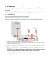
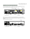
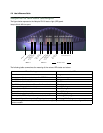
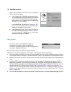
The figure below displays the back of the Netopia R3100 ISDN Router (models R3100-S, SP, U, UP).
Netopia R3100 ISDN Router back panel (models R3100 -S, SP, U, and UP)
Note: For simplicity, the remainder of this manual uses the figure above to illustrate connections.
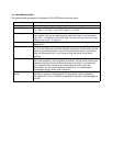
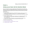
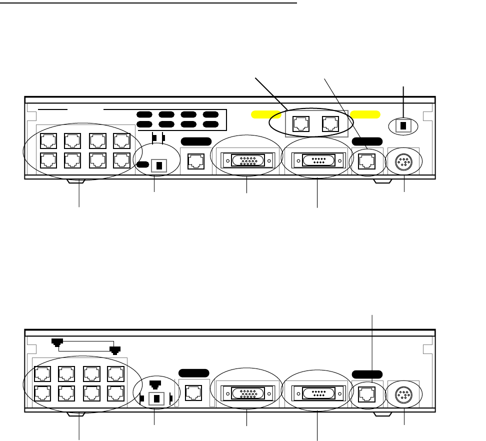
The figure below displays the back of the Netopia R3100 Router for Copper Mountain IDSL connections
(R3100-I).
Netopia R3100 IDSL back panel (model R3100-I)
8
Ethernet
Normal/Uplink
Auxiliary Console Power
4
7
3
6
2
5
1
Telco 2 Telco 1
Phone 1Phone 2
1
8 port Ethernet hub
Crossover switch
Line port
Auxiliary port
Console port
Power port
S/T Termination
switch
POTS ports (optional)
Ethernet
Normal
Auxiliary Console Power
Line 1
8 port Ethernet hub
Crossover switch
Line port
Auxiliary port
Console port
Power port
8
1
1
Uplink
Line 2