


2-4 User’s Reference Guide
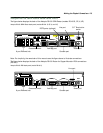
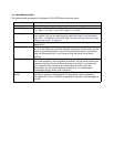
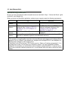
The following table describes all the Netopia R3100 ISDN Router back panel ports.
Port Description
Power port A mini-DIN8 power adapter cable connection.
Line or Telco port A telephone-style jack labelled “Telco1” or “Line” for your WAN connection. Use
the “Telco 1" or “Line 1" port, NOT “Telco 2" or “Line 2."
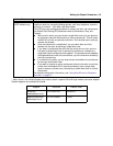
Console port A DE-9 console port for a direct serial connection to the console screens. You
can use this if you are an experienced user and don’t want to use the preset
192.168.1.1 IP address in the router. See “Connecting a local terminal console
cable to your router” on page 6-3.
Auxiliary port An HD-15 auxiliary port for attaching an external modem or the optional
AppleTalk kit.
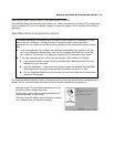
Crossover switch A crossover switch with Normal and Uplink positions. If you use Ethernet Port
#1 for a direct Ethernet connection between a computer and the router, set the
switch to the Normal position. If you are connecting the router to an Ethernet
hub, use Ethernet port #1 on the router and set the switch to the Uplink
position.
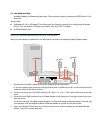
8-port Ethernet hub Eight Ethernet jacks. You will use one of these to configure the Netopia R3100.
For a new installation, use the Ethernet connection. You can either connect your
computer directly to any of the Ethernet ports on the router, or connect both
your computer and the router to an existing Ethernet hub on your LAN.
Alternatively, you can use the console connection to run console-based
management using a direct serial connection.
S/T Termination
switch
Netopia R3100 S/T models also provide an S/T termination switch. The S/T
termination switch on the Netopia R3100 back panel must be enabled to
terminate the S/T bus. To enable this parameter, the switch must be toggled to
the left.